VLT® 7000 Booster
Cascade Controller
Settings
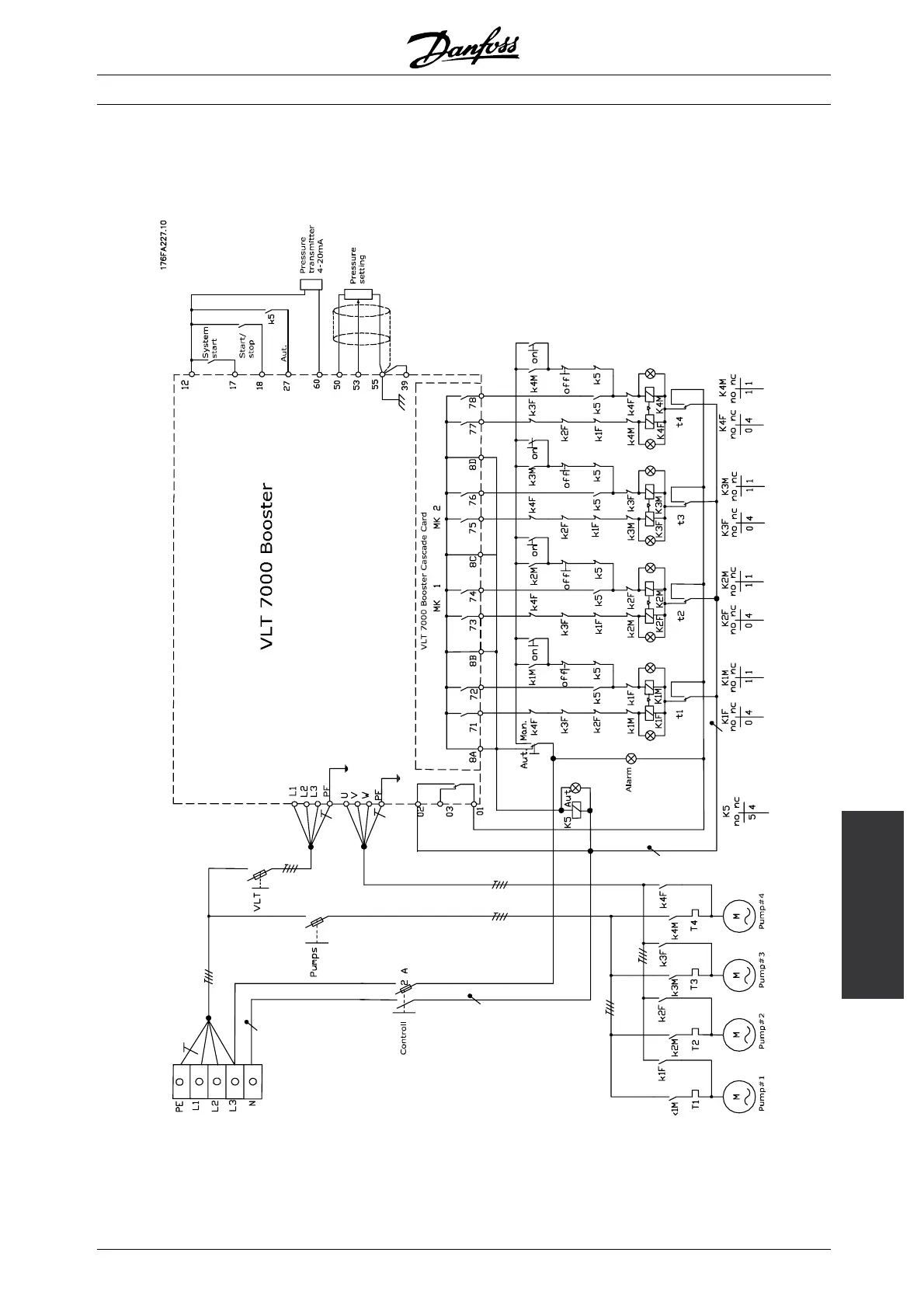
■ Wiring diagram modes 9-14
Please notice, that the DI18 functionality (terminal
18) depends on the mode selection. The diagram is
specifically made for modes 10, 12 and 14.
MG.70.A1.02 - VLT is a registered Danfoss trademark
97
 Loading...