Home
Danfoss
Extender
VLT 7000 Series
Page 96 (Wiring Diagram Mode 1-8)
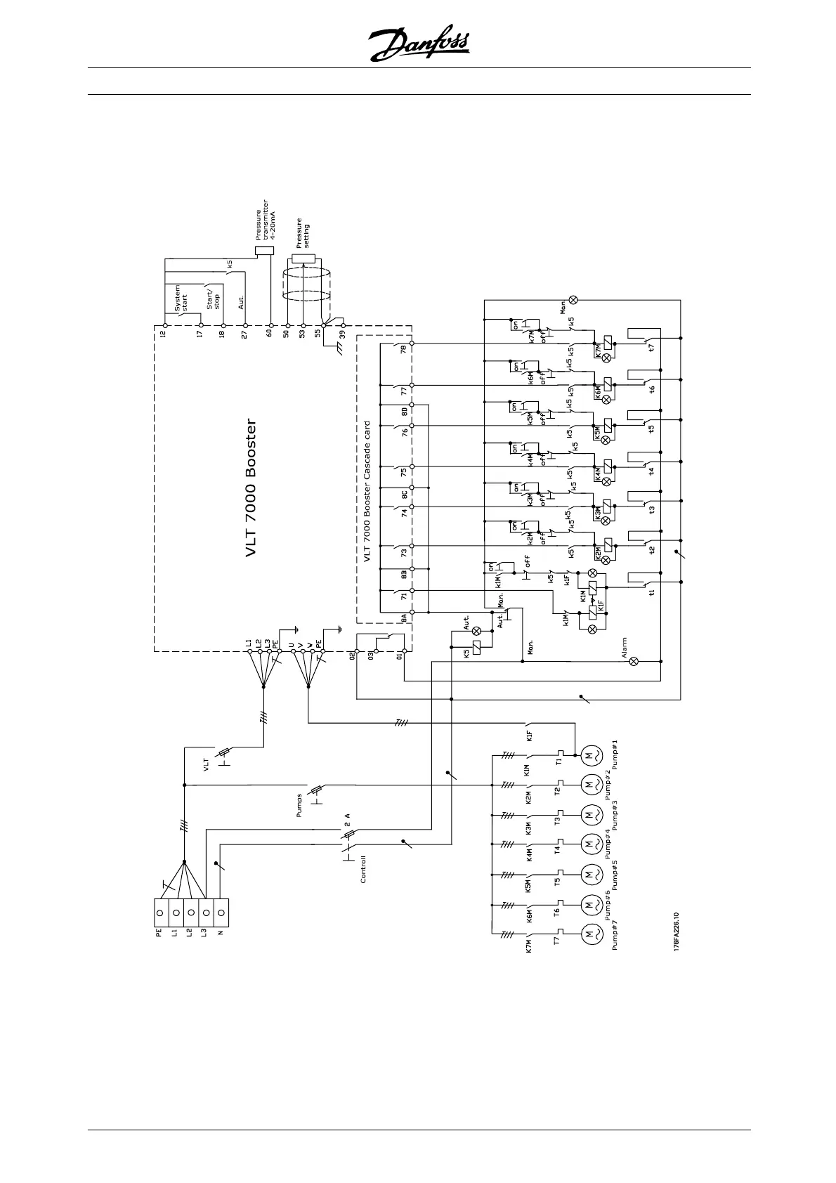
Danfoss VLT 7000 Series - Wiring Diagram Mode 1-8
141 pages
Manual
To Next Page
To Next Page
To Previous Page
To Previous Page
Loading...
VL
T®
7000
Booster
■
Wiring
diagram
mode
1-8
Please
n
otice,
that
the
DI18
functionality
(terminal
18)
depends
on
the
mode
selection.
Th
e
diagram
i
s
specifically
made
f
or
modes
2,
4,
6
and
8.
MG.7
0.A1.02
-
VL
T
is
a
regi
stere
d
Danf
oss
tradem
ark
96
95
97
Table of Contents
Main Page
Default Chapter
1
Table of Contents
1
Introduction to Booster
4
Software Version
4
Safety Regulations
5
Warning against Unintended Start
5
Introduction to Operating Instructions
7
Control Principle
8
AEO - Automatic Energy Optimization
9
PC Software and Serial Communication
10
Unpacking and Ordering a VLT Frequency Converter
11
Type Code Ordering Number String
11
Ordering Form
13
Installation
14
General Technical Data
14
Technical Data, Mains Supply 3 X 380-460V
18
Fuses
20
Mechanical Dimensions
21
Mechanical Installation
23
General Information about Electrical Installation
25
High Voltage Warning
25
Earthing
25
Cables
25
Screened/Armoured Cables
25
Extra Protection with Regard to Indirect Contact
25
RFI Switch
26
High Voltage Test
28
Heat Emission from VLT 7000 Booster
28
Ventilation of Integrated VLT 7000 Booster
28
EMC-Correct Electrical Installation
29
Use of EMC-Correct Cables
31
Electrical Installation - Earthing of Control Cables
32
Electrical Installation, Enclosures
33
Tightening-Up Torque and Screw Sizes
35
Mains Connection
35
Motor Connection
35
Direction of Motor Rotation
36
Motor Cables
36
Motor Thermal Protection
37
Earth Connection
37
DC Bus Connection
37
High-Voltage Relay
37
Control Card
37
Electrical Installation, Control Cables
38
Switches 1-4
39
Bus Connection
39
Programming
40
Control Unit LCP
40
Control Keys for Parameter Setup
40
Indicator Lamps
41
Local Control
41
Display Mode
42
Navigation between Display Modes
44
Changing Data
45
Manual Initialisation
45
Quick Menu
46
Operation and Display 001-017
48
The Setup Configuration
48
Setup of User-Defined Readout
49
Load and Motor 100-117
55
Configuration
55
Motor Power Factor (Cos Ø)
60
Inputs and Outputs 300-328
68
Analogue Inputs
69
Analogue/Digital Outputs
72
Relay Outputs
75
Application Functions 400-427
77
PID for Process Control
81
PID Overview
83
Feedback Handling
83
Service Functions 600-631
88
Cascade Controller Settings
93
Operation Modes
93
Mode no
93
Control Type
94
Fixed Lead Pump Control (Mode 1-8)
94
Alternating Lead Pump Control (Mode 9-14)
94
AUX Pump
94
Staging and Destaging Order
95
FILO: First In, Last out
95
LRHIMRHO: Least-Running-Hours-In, most Running-Hours out
95
Default Value for Digital Input on Terminal 18 (DI18)
95
No. of Pumps, Excl. AUX Pump
95
Wiring Diagram Mode 1-8
96
Wiring Diagram Modes 9-14
97
Parameter Settings
98
Quick Menu 17 Par. 700 Cascade Mode
98
Quick Menu 18 Par. 701 Pump Combination
98
Quick Menu 19 Par. 702 Staging Bandwidth
99
Quick Menu 20 Par. 703 SBW Destage Delay
99
Quick Menu 21 Par. 704 SBW Stage Delay
100
Quick Menu 22 Par. 705 Override Bandwidth
100
Quick Menu 23 Par. 706 Override Bandwidth Timer
101
Quick Menu 24 Par. 707 Destage by Timer
101
Staging and Destaging of Fixed Speed Pumps
102
Quick Menu 25 Par. 708 Staging Frequency
102
Quick Menu 26 Par. 709 Destaging Frequency
102
Staging and Destaging Og Fixed Speed Pumps
103
Quick Menu 27 Par. 710 Delay before Running on Mains
103
Auxiliary Pump/Sleep Mode
104
Quick Menu 28 Par. 711 Sleep/Aux Timer
104
Quick Menu 29 Par. 712 Sleep/Aux Frequency
104
Quick Menu 30 Par. 713 Wake Up/Disable Aux - Frequency
104
Quick Menu 31 Par. 714 Boost Setpoint
105
Virtual Control Curve
106
Example
106
Quick Menu 32 Par. 418 Setpoint 1
106
Quick Menu 33 Par. 419 Setpoint 2
106
Start and Stop Functionality
107
Quick Menu 34 Par. 719 Pump Enable
107
Quick Menu 35 Par. 720 Pump Running Hours
108
Feedback Transmitter Wiring
108
All about VLT 7000 Booster
110
Status Messages
110
List of Warnings and Alarms
112
Aggressive Environments
117
Calculation of Resulting Reference
117
Earth Leakage Current
118
Extreme Running Conditions
118
Peak Voltage on Motor
120
Switching on the Input
120
Acoustic Noise
121
Derating for Ambient Temperature
121
Derating for Air Pressure
122
Derating for Running at Low Speed
122
Derating for Long Motor Cables or Cables with Larger Cross-Section
122
Derating for High Switching Frequency
122
Vibration and Shock
123
Air Humidity
123
Efficiency
124
Mains Supply Interference/Harmonics
125
Power Factor
125
EMC Test Results (Emission, Immunity)
127
EMC Immunity
128
Definitions
130
Factory Settings
132
 Loading...