VLT® 7000 Booster
Installation
■ Tightening-up torque and screw sizes
The table shows the torque required when
fitting terminals to the frequency converter. For
VLT 7002-7072, 380-460 V the cables must
be fastened with screws.
These figures apply to the following terminals:
91, 92, 93
Mains terminals (Nos.) L1, L2, L3
96, 97, 98
Motor terminals (Nos.) U, V, W
Earth terminal (Nos.) 94, 95, 99
VLT type
3 x 380-460 V
Tightening-up
torque
Screw/bolt
size
Allen
key
size
VLT 7002-7011 0.5-0.6 Nm M3
VLT 7016-7027 1.8 Nm (IP 20) M4
VLT 7032-7052 3.0 Nm (IP 20) M5
3)
4mm
VLT 7062-7072 6.0 Nm M6
3)
5mm
1. Loadsharing terminals 14 Nm/M6, 5 mm Allen key
3. Allen screws (hexagon)
4. Loadsharing terminals 9.5 Nm/M8 (bolt)
■ Mains connection
Mains must be connected to terminals
91, 92, 93 Mains voltage 3 x 380-460 V
NB!:
Check that the mains voltage fits the mains
voltage of the frequency converter, which
can be seen from the nameplate.
See Technical data for correct sizing of cable
cross-sections.
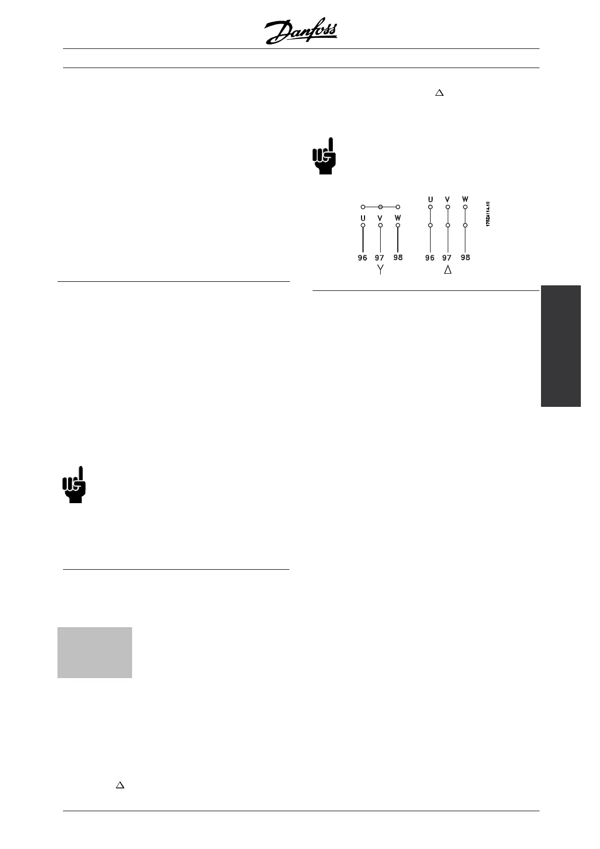
■ Motor connection
The motor must be connected to terminals 96,
97, 98. Earth to terminal 94/95/99.
Nos.
96. 97. 98
U, V, W
Motor voltage 0-100 % of mains voltage
No. 94/95/99 Earth connection
See Technical data for correct sizing of cable
cross-sections.
All types of three-phase asynchronous standard motors
can be used with a VLT 7000 Booster unit.
Small-size motors are normally star-connected.
(220/380 V,
/Y). Large-size motors are
delta-connected (380/660 V,
/Y). The correct
connection and voltage can be read from
the motor nameplate.
NB!:
In older motors without phase coil insulation,
a LC filter should be fitted to the frequency
converter output.
MG.70.A1.02 - VLT is a registered Danfoss trademark
35
 Loading...