VLT® 7000 Booster
■ Electrical installation, control cables
Torque: 0.5-0.6 Nm
Screw size: M3
Generally speaking, control cables must be screened/
armoured and the screen must be connected by means
of a cable clamp at both ends to the metal cabinet of
the unit (see Earthing of screened/ armoured control
cables). Normally, the screen must also be connected
to the body of the controlling unit (follow the instructions
for installation given for the unit in question).
If very long control cables are used, 50/60 Hz
earth loops may occur that will disturb the whole
system. This problem can be solved by connecting
one end of the screen to earth via a 100nF
condenser (keeping leads short).
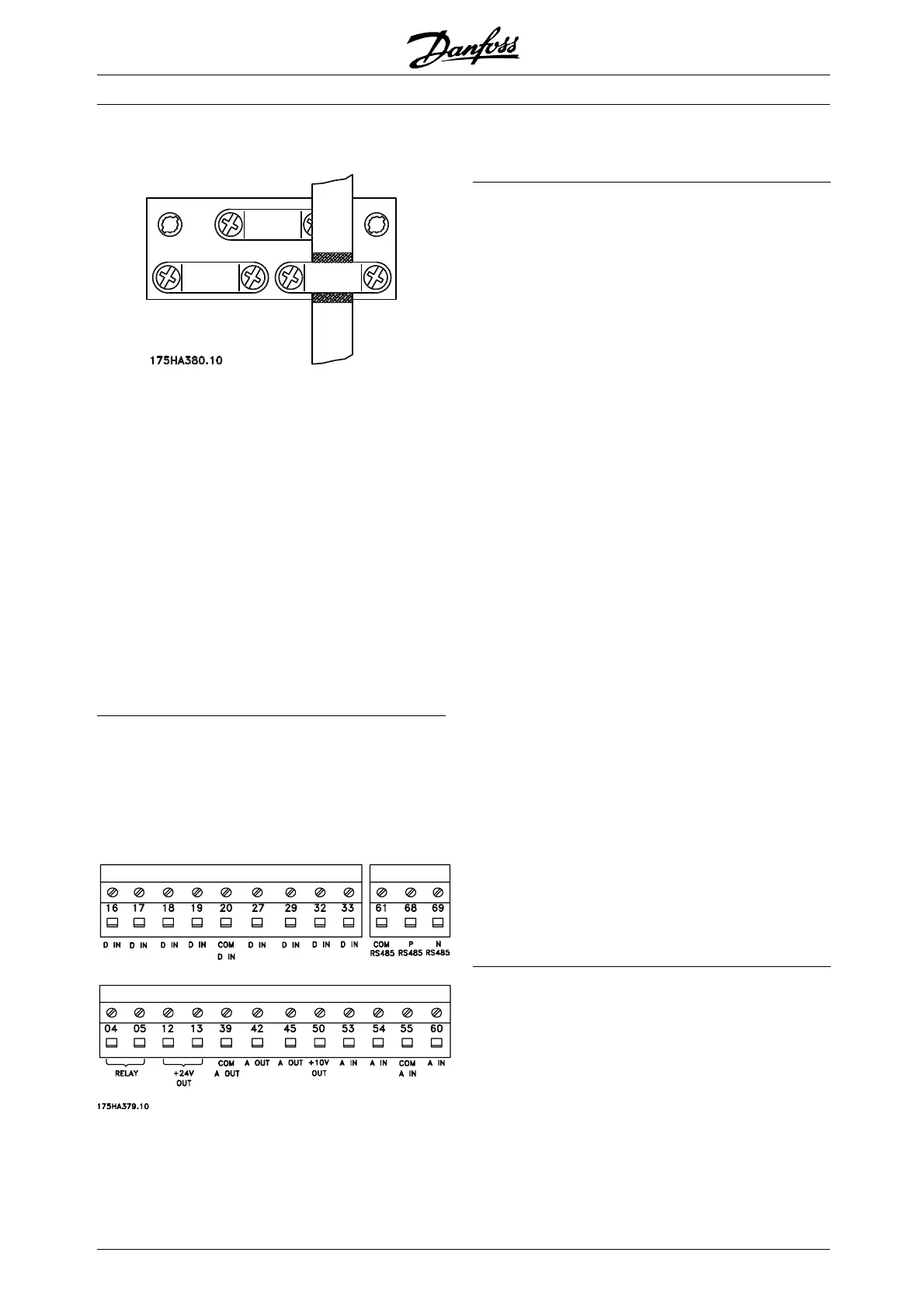
■ Electrical installation, control cables
Max. control cable cross section: 1.5 mm
2
/16 AWG
Torque: 0.5-0.6 Nm
Screw size: M3
See Earthing of screened/armoured control cables
for correct termination of control cables.
No. Function
04, 05 Relay output 2 can be used for indicating
status and warnings.
12, 13 Voltage supply to digital inputs. For the 24 V
DC to be used for digital inputs, switch 4 on
thecontrolcardmustbeclosed,position"on".
16-33 Digital inputs. See parameters 300-307 Digital
inputs.
20 Ground for digital inputs.
39 Ground for analogue/digital outputs. Must
be connnected to terminal 55 by means of
athree-wiretransmitter. SeeExamples of
connection.
42, 45 Analogue/digital outputs for indicating
frequency, reference, current and torque. See
parameters 319-322 Analogue/digital outputs.
50 Supply voltage to potentiometer and thermistor
10 V DC.
53, 54 Analogue voltage input, 0 - 10 V DC.
55 Ground for analogue voltage inputs.
60 Analogue current input 0/4-20 mA. See
parameters 314-316 Terminal 60.
61 Termination of serial communication. See
Earthing of screened/armoured c ontrol cables.
This terminal is not normally to be used.
68, 69 RS 485 interface, serial communication.
Where the frequency converter is connected
to a bus, switches 2 and 3 (switches 1- 4 -
see next page) must be closed on the first and
the last frequency converter. On the remaining
frequency converters, switches 2 and 3 must
be open. The factory setting is closed (position
on).
MG.70.A1.02 - VLT is a registered Danfoss trademark
38
 Loading...