VLT® 7000 Booster
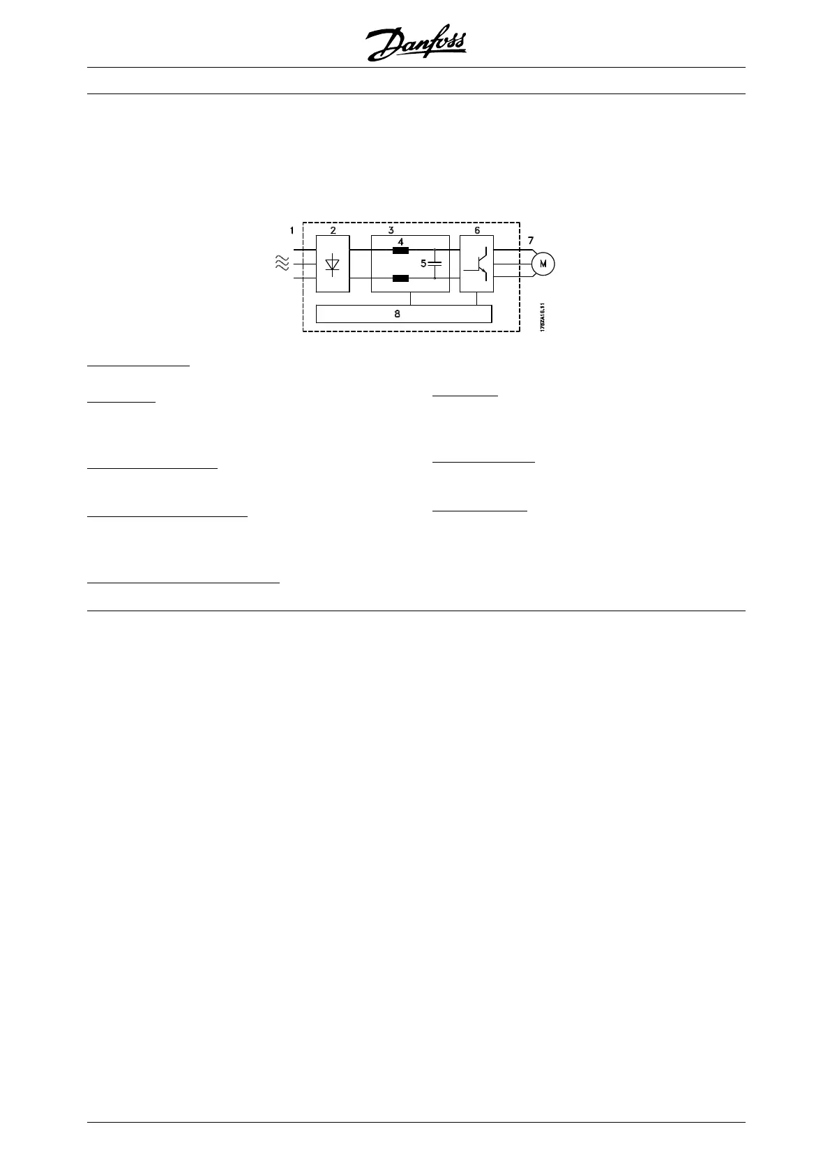
■ Control principle
A frequency converter rectifies AC voltage from
mains into DC voltage, after which this DC
voltage is converted into a AC current with a
variable amplitude and frequency.
The motor is thus supplied with variable voltage and
frequency, which enables infinitely variable speed
control of three-phased, standard AC motors.
1. Mains voltage
3 x 380 - 460 V AC, 50 / 60 Hz.
2
. Rectifier
A three-phase rectifier bridge that rectifies AC
current into DC current.
3
. Intermediate circuit
DC voltage = 1.35 x mains voltage [V].
4
. Intermediate circuit coils
Even out the intermediate circuit voltage and reduce
the harmonic current feedback to the mains supply.
5
. Intermediate circuit capacitors
Even out the intermediate circuit voltage.
6
. Inverter
Converts DC voltage into variable AC voltage
with a variable frequency.
7
. Motor voltage
Variable AC voltage, 0-100% of mains supply voltage.
8
. Control card
This is where to find the computer that controls
the inverter which generates the pulse pattern by
which the DC voltage is converted into variable
AC voltage with a variable frequency.
MG.70.A1.02 - VLT is a registered Danfoss trademark
8
 Loading...