VLT® 7000 Booster
All about VLT 7000
Booster
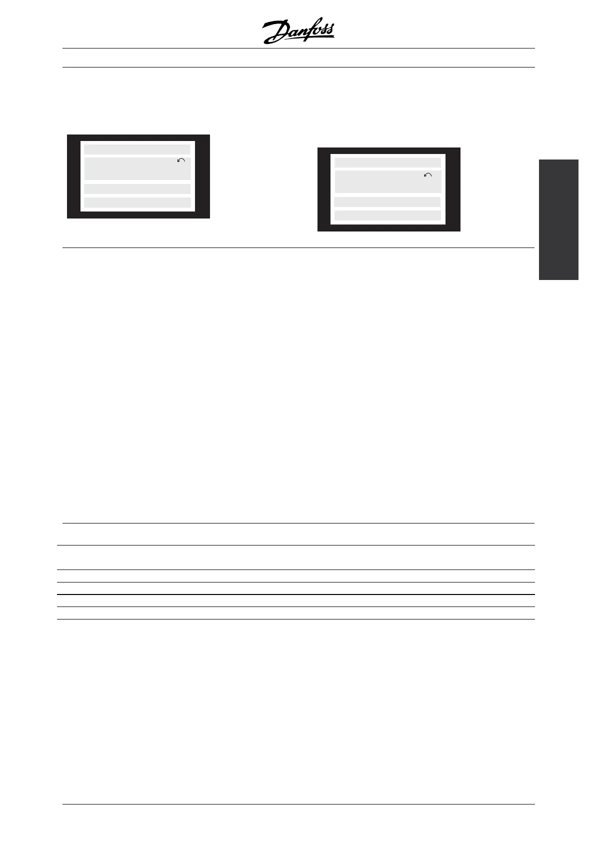
■ Warnings
A warning will flash in line 2, while an explanation
is given in line 1.
175ZA702.10
MAINS PHASE FAULT
WARN. 3
SETUP
1
■ Alarms
If an alarm is given, the present alarm number
will be shown in line 2. Lines 3 and 4 of the
display will offer an explanation.
175ZA703.10
SETUP
1
ALARM:12
TRIP (RESET)
CURRENT LIMIT
SETUP
1
WARNING 1
Under10V(10VOLTLOW)
The 10 V voltage from terminal 50 on the
control card is below 10 V.
Remove some of the load from terminal 50, as the 10
Volts supply is overloaded. Max. 17 mA/min. 590 .
WARNING/ALARM 2
Live zero fault (LIVE ZERO ERROR)
The current or voltage signal on terminal 53, 54 or
60 is below 50% of the value preset in parameter
309, 312 and 315 Terminal, min. scaling.
WARNING/ALARM 4
Mains imbalance (MAINS IMBALANCE)
High imbalance or phase missing on the supply side.
Check the supply voltage to the frequency converter.
WARNING 5
Voltage warning high (DC LINK VOLTAGE HIGH)
The intermediate circuit voltage (DC) is higher than
V oltage warning high, see table below. The controls
of the frequency converter are still enabled.
WARNING 6
Voltage warning low (DC LINK VOLTAGE LOW)
The intermediate circuit voltage (DC) is lower than
Voltage warning low, see table below. The controls
of the frequency converter are still enabled.
WARNING/ALARM 7
Overvoltage (DC LINK OVERVOLT)
If the intermediate circuit voltage (DC) is higher than
the Overvoltage limit of the inverter (see table below),
the frequency converter will trip after a fixed period.
The length of this period depends on the unit.
Alarm/warning limits:
VLT7000Booster 3x380-460V
[VDC]
Undervoltage 402
Voltage warning low 423
Voltage warning high 762
Overvoltage 798
The voltages stated are the intermediate circuit voltage of the frequency converter with a tolerance of ± 5 %.
The corresponding mains voltage is the intermediate circuit voltage divided by 1,35.
MG.70.A1.02 - VLT is a registered Danfoss trademark
113
 Loading...