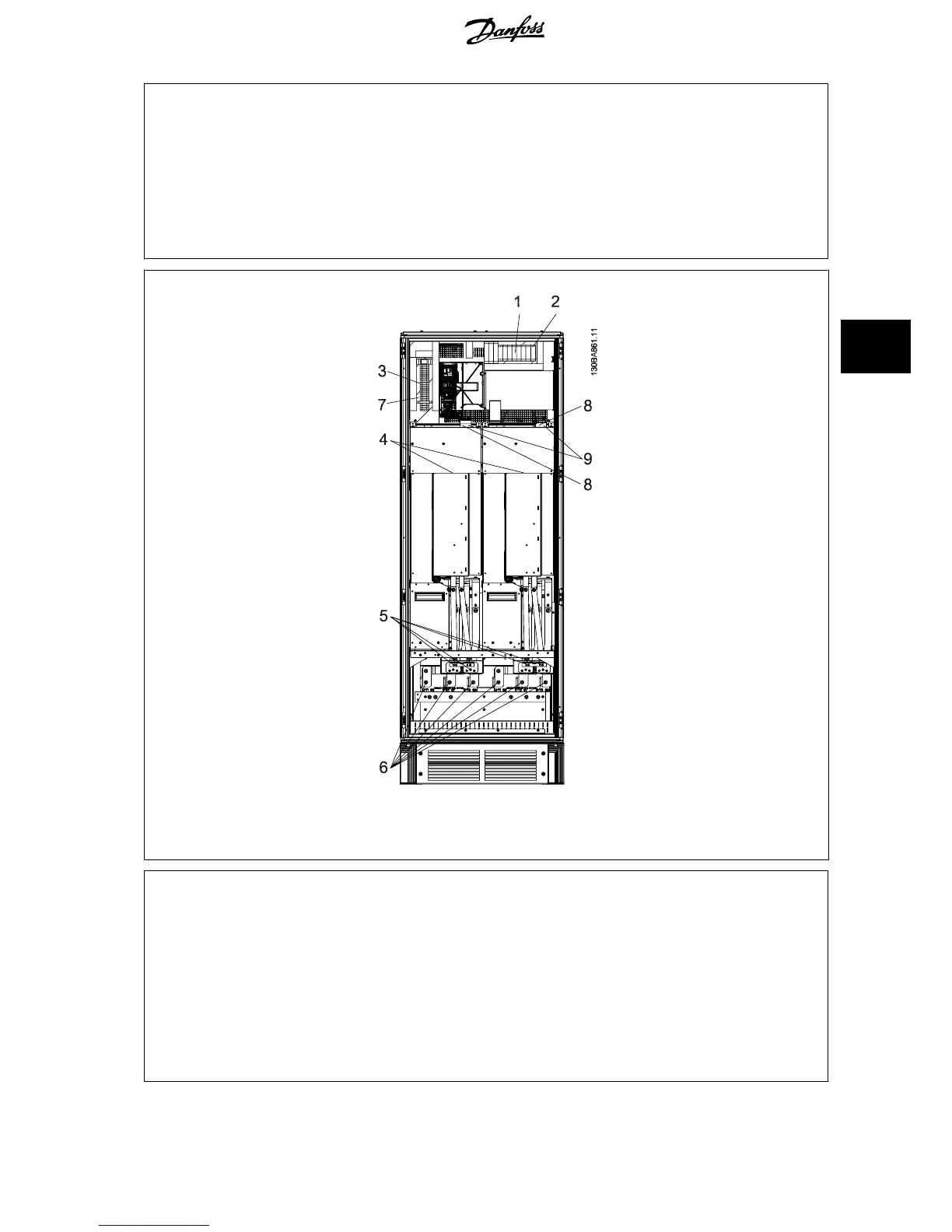
1) 24 V DC, 5 A 5) Loadsharing
T1 Output Taps -DC +DC
Temp Switch 88 89
106 104 105 6) Control Transformer Fuses (2 or 4 pieces). See fuse tables for part numbers
2) Manual Motor Starters 7) SMPS Fuse. See fuse tables for part numbers
3) 30 A Fuse Protected Power Terminals 8) Manual Motor Controller fuses (3 or 6 pieces). See fuse tables for part numbers
4) Line 9) Line Fuses, F1 and F2 frame (3 pieces). See fuse tables for part numbers
R S T 10) 30 Amp Fuse Protected Power fuses
L1 L2 L3
Illustration 5.33: Inverter Cabinet, frame size F1 and F3
1) External Temperature Monitoring 6) Motor
2) AUX Relay U V W
01 02 03 96 97 98
04 05 06 T1 T2 T3
3) NAMUR 7) NAMUR Fuse. See fuse tables for part numbers
4) AUX Fan 8) Fan Fuses. See fuse tables for part numbers
100 101 102 103 9) SMPS Fuses. See fuse tables for part numbers
L1 L2 L1 L2
5) Brake
-R +R
81 82
VLT
®
AQUA Drive Design Guide 5 How to Install
MG.20.N5.02 - VLT
®
is a registered Danfoss trademark
141
5
 Loading...


