Do not combine low voltage parts and PELV systems.
3.6.8 24 V Back-Up Option MCB 107 (Option D)
External 24 V DC Supply
An external 24 V DC supply can be installed for low-voltage supply to the
control card and any option card installed. This enables full operation of
the LCP (including the parameter setting) and field busses without mains
supplied to the power section.
External 24 V DC supply specification:
Input voltage range 24 V DC ±15 % (max. 37 V in 10 s)
Max. input current 2.2 A
Average input current for the frequency converter 0.9 A
Max cable length 75 m
Input capacitance load < 10 uF
Power-up delay < 0.6 s
The inputs are protected.
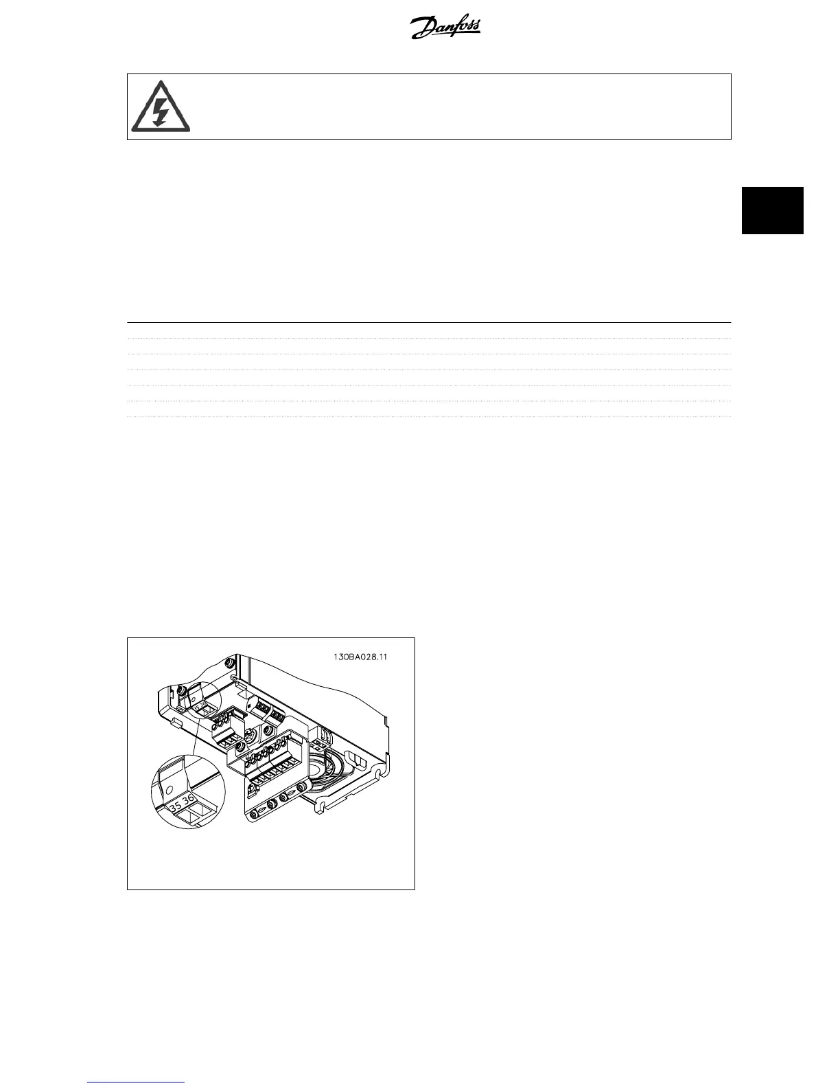
Terminal numbers:
Terminal 35: - external 24 V DC supply.
Terminal 36: + external 24 V DC supply.
Follow these steps:
1. Remove the LCP or Blind Cover
2. Remove the Terminal Cover
3. Remove the Cable De-coupling Plate and the plastic cover un-
derneath
4. Insert the 24 V DC Backup External Supply Option in the Option
Slot
5. Mount the Cable De-coupling Plate
6. Attach the Terminal Cover and the LCP or Blind Cover.
When MCB 107, 24 V backup option is supplying the control circuit, the
internal 24 V supply is automatically disconnected.
Illustration 3.21: Connection to 24 V backup supplier (A2-
A3).
VLT
®
AQUA Drive Design Guide 3 VLT AQUA Selection
MG.20.N5.02 - VLT
®
is a registered Danfoss trademark
71
3
 Loading...


