1. Use a clamp from the accessory bag to connect screen to fre-
quency converter decoupling plate for control cables.
See section entitled
Earthing of Screened/Armoured Control Cables
for
the correct termination of control cables.
Illustration 5.31: Control cable clamp.
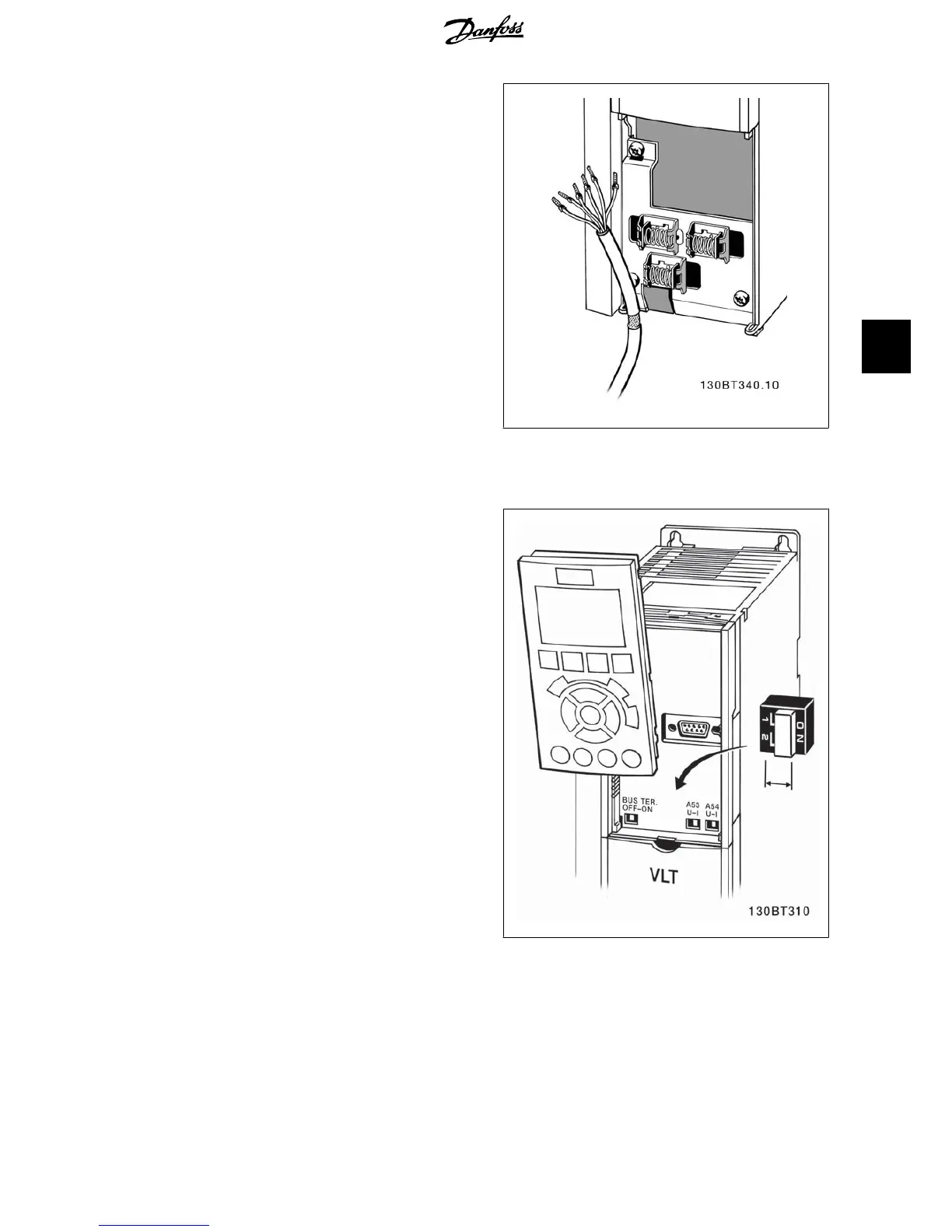
5.1.20. Switches S201, S202, and S801
Switches S201 (Al 53) and S202 (Al 54) are used to select a current (0-20
mA) or a voltage (0 to 10 V) configuration of the analog input terminals
53 and 54 respectively.
Switch S801 (BUS TER.) can be used to enable termination on the RS-485
port (terminals 68 and 69).
Please note that the switches may be covered by an option, if fitted.
Default setting:
S201 (AI 53) = OFF (voltage input)
S202 (AI 54) = OFF (voltage input)
S801 (Bus termination) = OFF
Illustration 5.32: Switches location.
VLT
®
AQUA Drive
Operating Instructions
5. Electrical installation
MG.20.M4.02 - VLT
®
is a registered Danfoss trademark
41
5