7.1.11. Initialisation to Default Settings
There are two ways to initialise the frequency converter to default: Recommended initialisation and manual initialisation.
Please be aware that they have different impact according to the below description.
Recommended initialisation (via par. 14-22)
1. Select par. 14-22
2. Press [OK]
3. Select “Initialisation” ( for NLCP select “2” )
4. Press [OK]
5. Remove power to unit and wait for display to turn off.
6. Reconnect power and the frequency converter is reset. Note
that first start-up takes a few more seconds.
7. Press [Reset]
Par. 14-22 initialises all except:
Par. 14-50
RFI 1
Par. 8-30
Protocol
Par. 8-31
Address
Par. 8-32
Baud Rate
Par. 8-35
Minimum Response Delay
Par. 8-36
Max Response Delay
Par. 8-37
Max Inter-char Delay
Par. 15-00 to par.
15-05
Operating data
Par. 15-20 to par.
15-22
Historic log
Par. 15-30 to par.
15-32
Fault log
NB!
Parameters selected in
Personal Menu
, will stay present, with default factory setting.
Manual initialisation
NB!
When carrying out manual initialisation, serial communication, RFI filter settings (par. 14-50) and fault log settings are reset.
Removes parameters selected in
Personal Menu
.
1. Disconnect from mains and wait until the display turns off.
2a. Press [Status] - [Main Menu] - [OK] at the same time while
power up for Graphical LCP (GLCP).
2b. Press [Menu] while power up for LCP 101, Numerical Display
3. Release the keys after 5 s.
4. The frequency converter is now programmed according to
default settings.
This parameter initialises all except:
15-00
Operating Hours
15-03
Power-up's
15-04
Over temp's
15-05
Over volt's
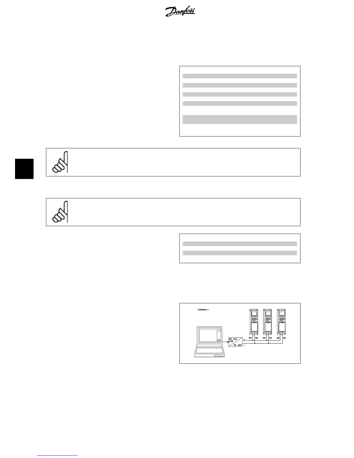
7.1.12. RS-485 Bus Connection
One or more frequency converters can be connected to a controller (or
master) using the RS-485 standard interface. Terminal 68 is connected
to the P signal (TX+, RX+), while terminal 69 is connected to the N signal
(TX-,RX-).
If more than one frequency converter is connected to a master, use par-
allel connections.
Illustration 7.9: Connection example.
7. How to operate the frequency converter
VLT
®
AQUA Drive
Operating Instructions
58
MG.20.M4.02 - VLT
®
is a registered Danfoss trademark
7