EXAMPLE 2:
Variable= FEEDBACK, range= -200% to +200%
Range needed for output= 0-100%
Output signal 0 or 4 mA is needed at 0% (50% of range) - set par. 6-51 to 50%
Output signal 20 mA is needed at 100% (75% of range) - set par. 6-52 to 75%
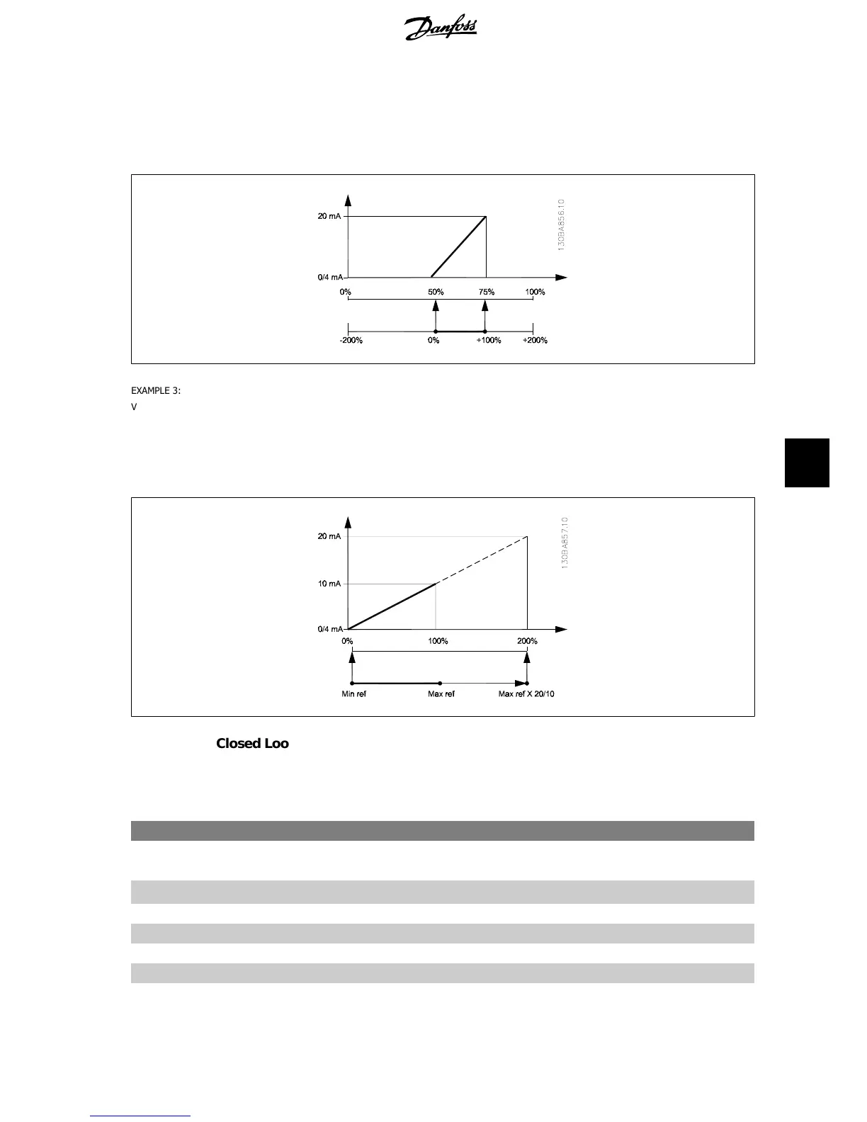
EXAMPLE 3:
Variable value= REFERENCE, range= Min ref - Max ref
Range needed for output= Min ref (0%) - Max ref (100%), 0-10 mA
Output signal 0 or 4 mA is needed at Min ref - set par. 6-51 to 0%
Output signal 10 mA is needed at Max ref (100% of range) - set par. 6-52 to 200%
(20 mA / 10 mA x 100%=200%).
8.2.9. Drive Closed Loop, 20-**
This parameter group is used for configuring the closed loop PID Controller, that controls the output frequency of the frequency converter.
20-12 Reference/Feedback Unit
Option: Function:
[0] None
[1]
*
%
[5] PPM
[10] 1/min
[11] RPM
[12] Pulse/s
[20] l/s
VLT
®
AQUA Drive
Operating Instructions
8. How to programme the frequency converter
MG.20.M4.02 - VLT
®
is a registered Danfoss trademark
85
8
 Loading...


