11.2.23 Twistlock DC Capacitor Bank Layouts
Twistlock DC capacitor banks dier in the number of capacitors and plugs present and the location of fasteners, such as
screws and standos. The drive size and power rating determine the layout of the twistlock DC capacitor bank. Use
Table 11.5 to Table 11.7 to nd the twistlock DC capacitor bank layout for a particular drive in D2h/D4h/D7h/D8h/J9 sizes.
Graphic reference Model
FC 102, FC 103, and FC 202 FC 302
Illustration 11.25 N90K N75K
Illustration 11.25 N110 N90K
Illustration 11.26 N150 N110
Illustration 11.27 N160 N150
Table 11.5 Twistlock DC Capacitor Bank Layout 200–240 V
Graphic reference Model
FC 102, FC 103, and FC 202 FC 302
Illustration 11.25 N200 N160
Illustration 11.26 N250 N200
Illustration 11.27 N315 N250
Table 11.6 Twistlock DC Capacitor Bank Layout 380–500 V
Graphic reference Model
FC 102, FC 103, and FC 202 FC 302
Illustration 11.28 N200 N160
Illustration 11.28 N250 N200
Illustration 11.29 N315 N250
Illustration 11.29 N400 N315
Table 11.7 Twistlock DC Capacitor Bank Layout 525–690 V
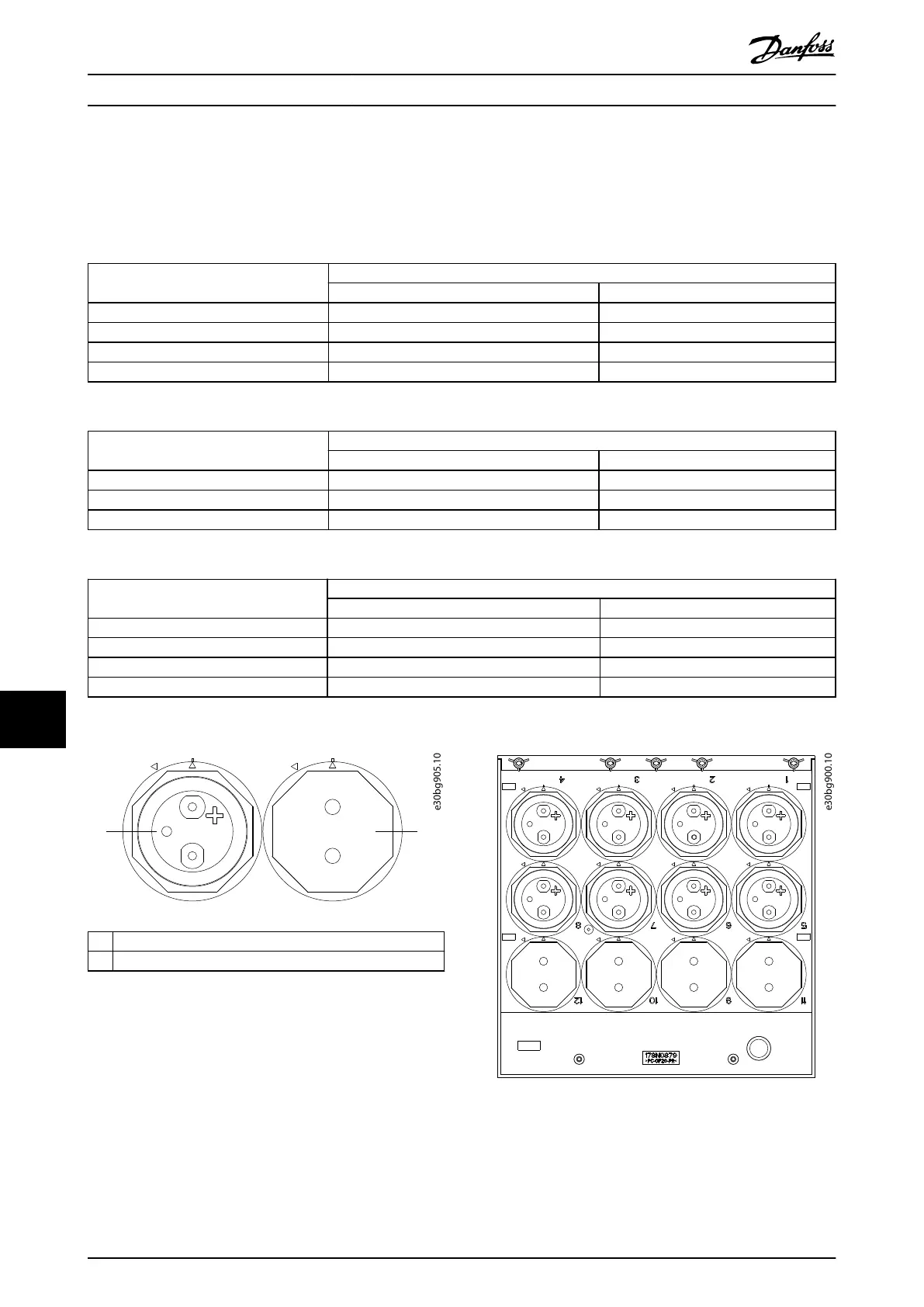
1 Twistlock DC capacitor
2 Plug
Illustration 11.24 Twistlock DC Capacitor and Plug
Illustration 11.25 Twistlock 8-Capacitor Layout
D2h/D4h/D7h/D8h/J9 Unit Dis...
VLT
®
FC Series, D1h–D8h, Da2/Db2/Da4/Db4, E1h–E4h, J8/J9
228 Danfoss A/S © 02/2019 All rights reserved. MG94A502
1111

 Loading...


