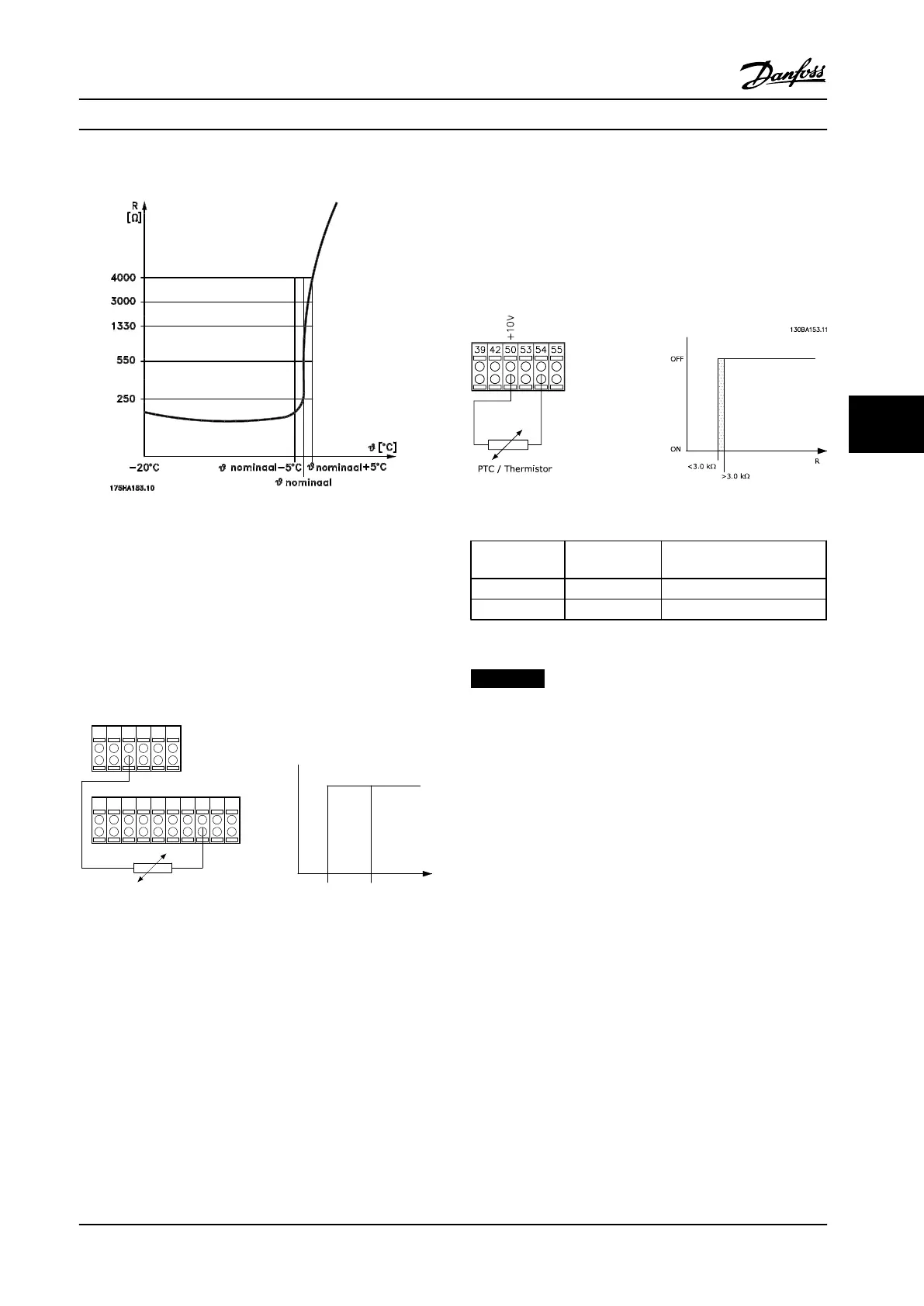
PTC Thermistor Connection
Figure 6.2 PTC profile
Using a digital input and 10 V as power supply:
Example: The adjustable frequency drive trips when the
motor temperature is too high.
Parameter set-up:
Set parameter 1-90 Motor Thermal Protection to [2]
Thermistor Trip
Set parameter 1-93 Thermistor Source to [6] Digital Input
PTC / Thermistor
R
OFF
ON
<800 Ω
+10V
130BA152.10
>2.7 kΩ
12 13 18 37322719 29 33 20
5550
39 42 53 54
Figure 6.3 Example with Digital Input and 10 V Power Supply
Using an analog input and 10 V as power supply:
Example: The adjustable frequency drive trips when the
motor temperature is too high.
Parameter set-up:
Set parameter 1-90 Motor Thermal Protection to [2]
Thermistor Trip
Set parameter 1-93 Thermistor Source to [2] Analog Input 54
Figure 6.4 Example with Analog Input and 10 V Power Supply
Input
Digital/analog
Supply Voltage
[V]
Threshold
Cut-out Values
Digital 10
< 800 Ω - > 2.7 kΩ
Analog 10
< 3.0 kΩ - > 3.0 kΩ
Table 6.2 Threshold Cut-out Values for Figure 6.3 and Figure 6.4
NOTICE!
Check that the selected supply voltage follows the
specification of the thermistor element.
Programming Instruction Manual
MG37A222 Danfoss A/S © Rev. 2014-02-07 All rights reserved. 57
6 6

 Loading...


