3-10 Preset Reference
Array [8]
Range: 0–7
Range: Function:
0 %* [-100 - 100 %]
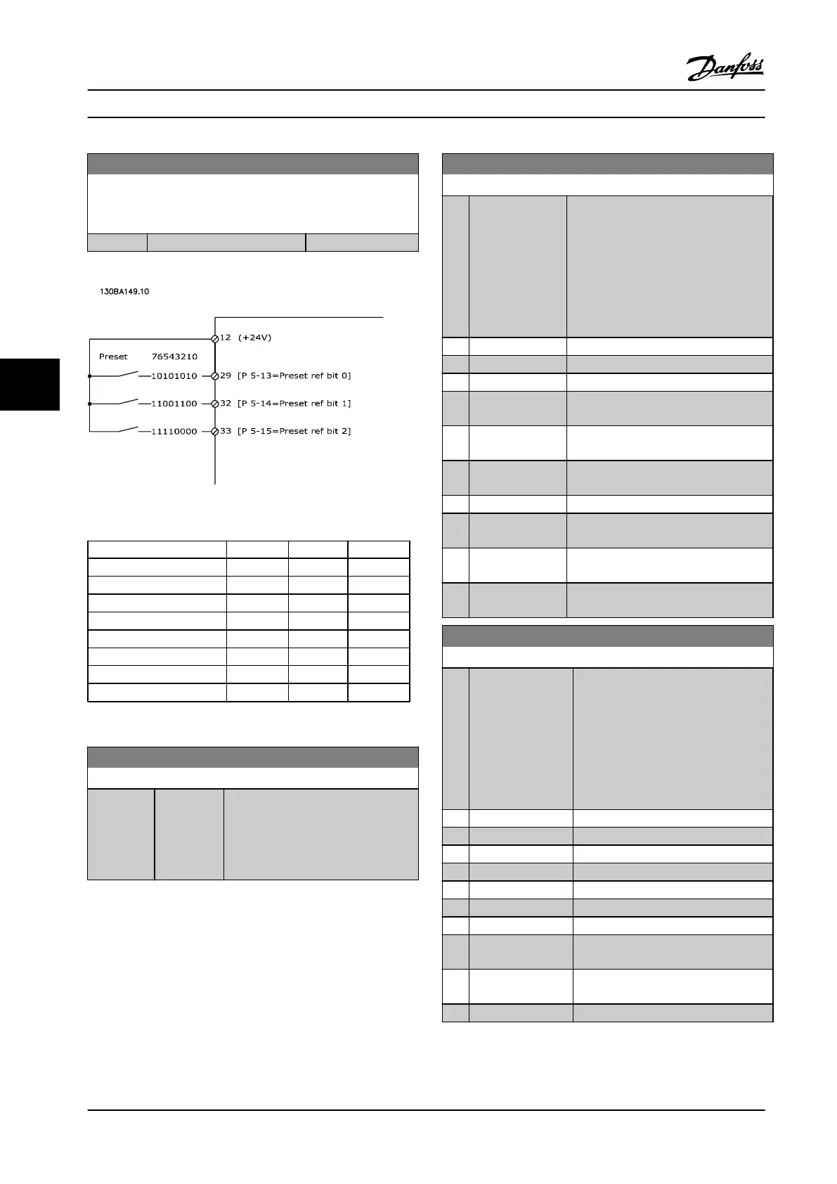
Figure 6.9 Preset Reference
Preset ref. bit 2 1 0
Preset ref. 0 0 0 0
Preset ref. 1 0 0 1
Preset ref. 2 0 1 0
Preset ref. 3 0 1 1
Preset ref. 4 1 0 0
Preset ref. 5 1 0 1
Preset ref. 6 1 1 0
Preset ref. 7 1 1 1
Table 6.4 Bits per Preset Reference
3-11 Jog Speed [Hz]
Range: Function:
Size
related*
[ 0 - par.
4-14 Hz]
The jog speed is a fixed output speed
at which the adjustable frequency
drive is running when the jog
function is activated.
See also 3-80 Jog Ramp Time.
3-15 Reference Resource 1
Option: Function:
Select the reference input to be used
for the first reference signal.
parameter 3-15 Reference Resource 1,
parameter 3-16 Reference Resource 2 and
parameter 3-17 Reference Resource 3
define up to three different reference
signals. The sum of these reference
signals defines the actual reference.
[0] No function
[1] Analog Input 53
[2] Analog Input 54
[7] Frequency input
29
[8] Frequency input
33
[11] Local bus
reference
[20] Digital pot.meter
[21] Analog input
X30-11
(General Purpose I/O Option Module)
[22] Analog input
X30-12
(General Purpose I/O Option Module)
[29] Analog Input
X48/2
3-16 Reference Resource 2
Option: Function:
Select the reference input to be used
for the second reference signal.
parameter 3-15 Reference Resource 1,
parameter 3-16 Reference Resource 2
and parameter 3-17 Reference Resource
3 define up to three different reference
signals. The sum of these reference
signals defines the actual reference.
[0] No function
[1] Analog Input 53
[2] Analog Input 54
[7] Frequency input 29
[8] Frequency input 33
[11] Local bus reference
[20] Digital pot.meter
[21] Analog input
X30-11
[22] Analog input
X30-12
[29] Analog Input X48/2
Programming Instruction Manual
64 Danfoss A/S © Rev. 2014-02-07 All rights reserved. MG37A222
66

 Loading...


