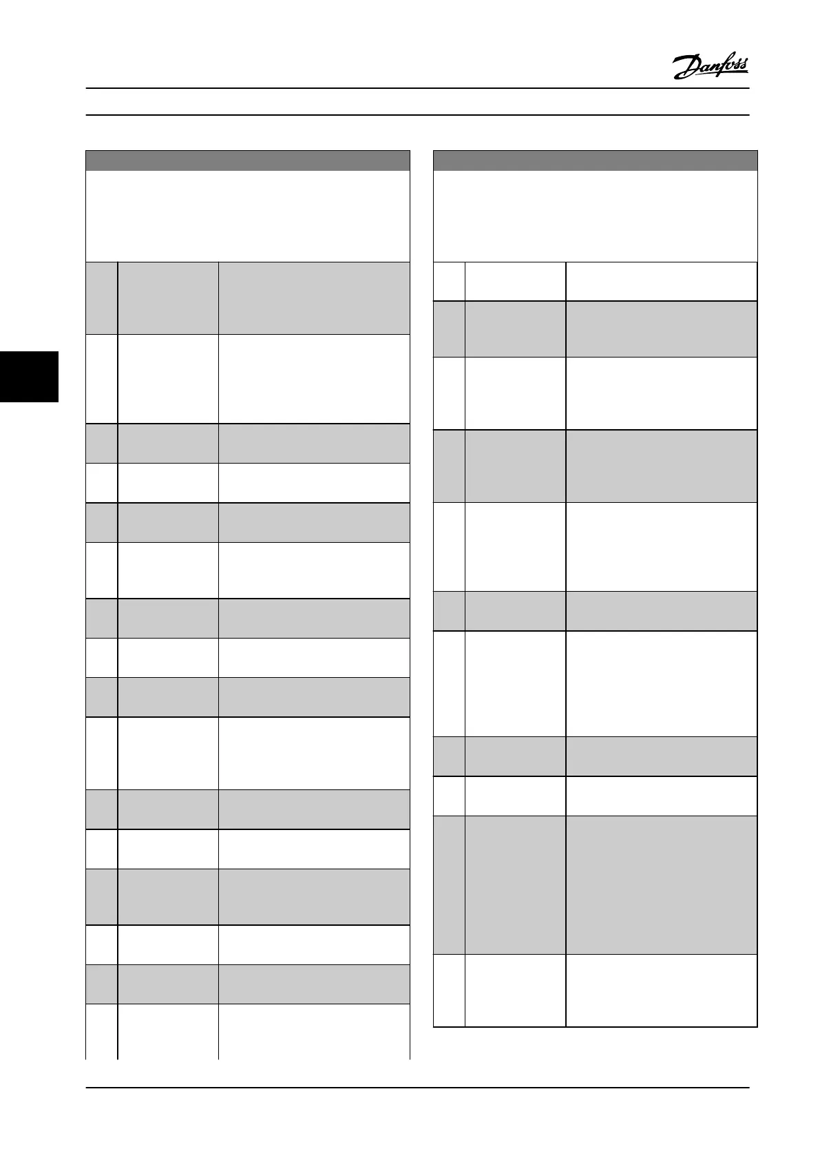
5-40 Function Relay
Array [9]
(Relay 1 [0], Relay 2 [1], Relay 3 [2] (MCB 113), Relay 4 [3] (MCB
113), Relay 5 [4] (MCB 113), Relay 6 [5] (MCB 113), Relay 7 [6]
(MCB 105), Relay 8 [7] (MCB 105), Relay 9 [8] (MCB 105))
Option: Function:
[6] Running / no
warning
Output speed is higher than the
speed set in 1-81 Min Speed for
Function at Stop [RPM]. The motor is
running and no warnings are active.
[7] Run in range/no
warn
Motor is running within the
programmed current and speed
ranges set in 4-50 Warning Current
Low and 4-53 Warning Speed High. No
warnings are active.
[8] Run on ref/no
warn
Motor runs at reference speed. No
warnings are active.
[9] Alarm An alarm activates the output. No
warnings are active.
[10] Alarm or warning An alarm or a warning activates the
output.
[11] At torque limit
The torque limit set in 4-16 Torque
Limit Motor Mode or 4-17 Torque Limit
Generator Mode has been exceeded.
[12] Out of current
range
The motor current is outside the
range set in .
[13] Below current, low Motor current is lower than that set
in 4-50 Warning Current Low.
[14] Above current,
high
Motor current is higher than that set
in 4-51 Warning Current High.
[15] Out of speed
range
Output speed/frequency is outside
the frequency ranges set in
4-52 Warning Speed Low and
4-53 Warning Speed High.
[16] Below speed, low Output speed is lower than the
setting in 4-52 Warning Speed Low
[17] Above speed, high Output speed is higher than the
setting in 4-53 Warning Speed High.
[18] Out of feedb.
range
Feedback is outside the range set in
4-56 Warning Feedback Low and
4-57 Warning Feedback High.
[19] Below feedback,
low
Feedback is below the limit set in
4-56 Warning Feedback Low.
[20] Above feedback,
high
Feedback is above the limit set in
4-57 Warning Feedback High.
[21] Thermal warning Thermal warning turns on when the
temperature exceeds the limit either
in motor, adjustable frequency drive,
5-40 Function Relay
Array [9]
(Relay 1 [0], Relay 2 [1], Relay 3 [2] (MCB 113), Relay 4 [3] (MCB
113), Relay 5 [4] (MCB 113), Relay 6 [5] (MCB 113), Relay 7 [6]
(MCB 105), Relay 8 [7] (MCB 105), Relay 9 [8] (MCB 105))
Option: Function:
brake resistor, or connected
thermistor.
[22] Ready,no thermal
W
The adjustable frequency drive is
ready for operation and there is no
overtemperature warning.
[23] Remote,ready,no
TW
The adjustable frequency drive is
ready for operation and is in Auto On
mode. There is no overtemperature
warning.
[24] Ready, Voltage OK The adjustable frequency drive is
ready for operation and the AC line
voltage is within the specified voltage
range (see chapter 11 Specifications).
[25] Reverse Logic ‘1’ when CW rotation of the
motor. Logic ‘0’ when CCW rotation of
the motor. If the motor is not
rotating, the output follows the
reference.
[26] Bus OK Active communication (no timeout)
via the serial communication port.
[27] Torque limit stop Use in performing a coasted stop and
adjustable frequency drive in torque
limit condition. If the adjustable
frequency drive has received a stop
signal and is at the torque limit, the
signal is Logic ‘0’.
[28] Brake: No Brake
War
Brake is active and there are no
warnings.
[29] Brake ready, no
fault
Brake is ready for operation and there
are no faults.
[30] Brake fault (IGBT) Output is Logic ‘1’ when the brake
IGBT is short-circuited. Use this
function to protect the adjustable
frequency drive if there is a fault on
the brake module. Use the digital
output/relay to cut out the AC line
voltage from the adjustable frequency
drive.
[31] Relay 123 Digital output/relay is activated when
Control Word [0] is selected in
parameter group 8-** Communication
and Options..
Programming Instruction Manual
72 Danfoss A/S © Rev. 2014-02-07 All rights reserved. MG37A222
66

 Loading...


