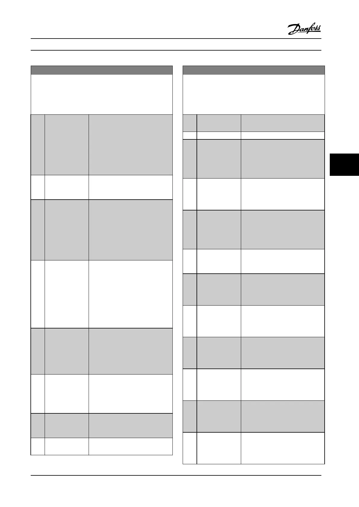
5-40 Function Relay
Array [9]
(Relay 1 [0], Relay 2 [1], Relay 3 [2] (MCB 113), Relay 4 [3] (MCB
113), Relay 5 [4] (MCB 113), Relay 6 [5] (MCB 113), Relay 7 [6]
(MCB 105), Relay 8 [7] (MCB 105), Relay 9 [8] (MCB 105))
Option: Function:
[32] Mech brake ctrl Selection of mechanical brake control.
When selected parameters in
parameter group 2-2* Mechanical
Brake are active. The output must be
reinforced to carry the current for the
coil in the brake. Solved by
connecting an external relay to the
selected digital output.
[33] Safe stop active (FC 302 only) Indicates that the safe
stop on terminal 37 has been
activated.
[36] Control word bit
11
Activate relay 1 via control word from
serial communication bus. No other
functional impact in the adjustable
frequency drive. Typical application:
Controlling auxiliary devices from
serial communication bus. The
function is valid when [0] FC profile in
8-10 Control Word Profile is selected.
[37] Control word bit
12
Activate relay 2 (FC 302 only) by
control word from serial communi-
cation bus. No other functional
impact in the adjustable frequency
drive. Typical application: controlling
auxiliary device from the serial
communication bus. The function is
valid when [0] FC profile in
8-10 Control Word Profile is selected.
[38] Motor feedb. error Failure in the speed feedback loop
from motor running in closed-loop.
The output can eventually be used to
prepare switching the adjustable
frequency drive in open-loop in the
case of an emergency.
[39] Tracking error When the difference between
calculated speed and actual speed in
4-35 Tracking Error is larger than
selected the digital output/relay is
active.
[40] Out of ref range Active when the actual speed is
outside settings in 4-52 Warning Speed
Low to 4-55 Warning Reference High.
[41] Below reference,
low
Active when actual speed is below
speed reference setting.
5-40 Function Relay
Array [9]
(Relay 1 [0], Relay 2 [1], Relay 3 [2] (MCB 113), Relay 4 [3] (MCB
113), Relay 5 [4] (MCB 113), Relay 6 [5] (MCB 113), Relay 7 [6]
(MCB 105), Relay 8 [7] (MCB 105), Relay 9 [8] (MCB 105))
Option: Function:
[42] Above ref, high Active when actual speed is above
speed reference setting.
[43] Extended PID Limit
[45] Bus ctrl. Controls digital output/relay via bus.
The state of the output is set in
5-90 Digital & Relay Bus Control. The
output state is retained in the event
of bus timeout.
[46] Bus ctrl, 1 if
timeout
Controls output via bus. The state of
the output is set in 5-90 Digital &
Relay Bus Control. If bus timeout, the
output state is set high (On).
[47] Bus ctrl, 0 if
timeout
Controls output via bus. The state of
the output is set in 5-90 Digital &
Relay Bus Control. In the event of a
bus timeout, the output state is set to
low (Off).
[51] MCO controlled Active when an MCO 302 or MCO 305
is connected. The output is controlled
from an option.
[60] Comparator 0
See parameter group 13-1* Smart
Logic Control. If Comparator 0 in SLC
is true, the output goes high.
Otherwise, it is low.
[61] Comparator 1
See parameter group 13-1* Smart
Logic Control. If Comparator 1 in SLC
is true, the output goes high.
Otherwise, it is low.
[62] Comparator 2
See parameter group 13-1* Smart
Logic Control. If Comparator 2 in SLC
is true, the output goes high.
Otherwise, it is low.
[63] Comparator 3
See parameter group 13-1* Smart
Logic Control. If Comparator 3 in SLC
is true, the output goes high.
Otherwise, it is low.
[64] Comparator 4
See parameter group 13-1* Smart
Logic Control. If Comparator 4 in SLC
is true, the output goes high.
Otherwise, it is low.
[65] Comparator 5
See parameter group 13-1* Smart
Logic Control. If Comparator 5 in SLC
is true, the output goes high.
Otherwise, it is low.
Programming Instruction Manual
MG37A222 Danfoss A/S © Rev. 2014-02-07 All rights reserved. 73
6 6

 Loading...


