130BD600.10
CHASSIS/ IP20 Tamb.50
C/122 F
V LT
MADE IN DENMARK
R
P/N: 131X3537 S/N: 010122G430
0.37kW/ 0.50HP
IN: 3x200-240V 50/60Hz 2.2A
OUT: 3x0-Vin 0-1000Hz 2.4A
o
CAUTION:
See manual for special condition/mains fuse
voir manual de conditions speclales/fusibles
WARNING:
Stored charge, wait 4 min.
Charge residuelle, attendez 4 min.
* 1 3 1
X
3 5 3 7 0 1 0 1 2 2 G 4 3 0 *
`
Automation Drive
www.danfoss.com
T/C: FC-302PK37T2E20H1BGXXXXSXXXXA6BKC4XXXD0
Listed 76X1 E134261 Ind. Contr. Eq.
o
`
1
2
4
5
6
7
8
9
10
3
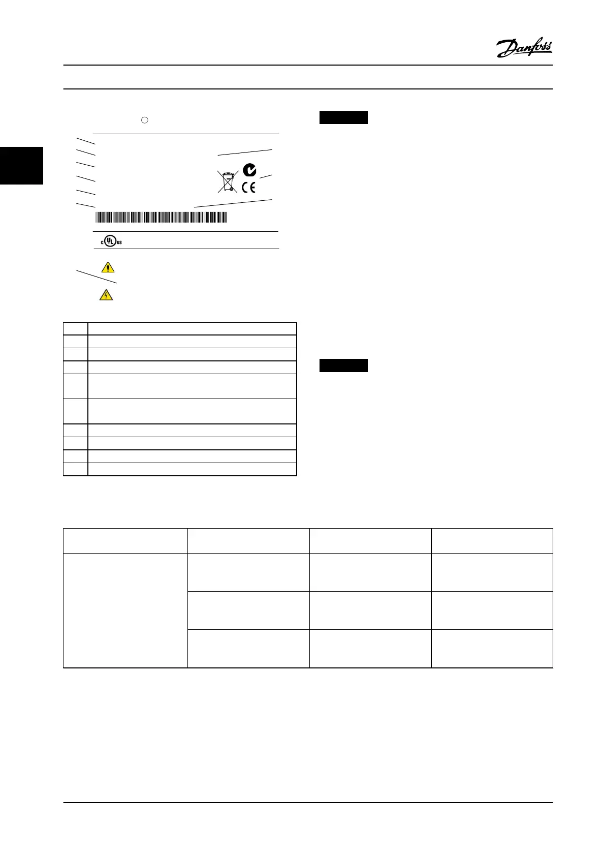
1 Type code
2 Order number
3 Serial number
4 Power rating
5
Input voltage, frequency and current (at low/high
voltages)
6
Output voltage, frequency and current (at low/high
voltages)
7 Enclosure type and IP rating
8 Maximum ambient temperature
9 Certications
10 Discharge time (Warning)
Figure 3.1 Product Nameplate (Example)
NOTICE!
Do not remove the nameplate from the adjustable
frequency drive (loss of warranty).
3.3 Mechanical Installation
3.3.1 Cooling and Airow
Cooling
Cooling can be obtained in dierent ways, by using the
cooling ducts in the bottom and the top of the unit, by
taking air in and out the back of the unit or by combining
the cooling possibilities.
Back cooling
The backchannel air can also be ventilated in and out the
back of a Rittal TS8 enclosure for frame size F18 LHD. This
oers a solution where the backchannel could take air
from outside the facility and return the heat losses outside
the facility thus reducing air-conditioning requirements.
NOTICE!
A door fan is required on the enclosure to remove the
heat losses not contained in the backchannel of the
drive and any additional losses generated from other
components installed inside the enclosure. The total
required air ow must be calculated so that the
appropriate fans can be selected. Some enclosure
manufacturers oer software for performing the
calculations (i.e., Rittal Therm software).
Airow
The necessary airow over the heatsink must be ensured.
The ow rate is shown in Table 3.1.
Enclosure protection Frame size
Door fan/top fan airow
Total airow of multiple fans
Heatsink fan
Total airow for multiple fans
IP21/NEMA 1
IP54/NEMA 12
D13
(LHD120)
3 door fans, 510 m
3
/h (300 cfm)
(2+1, 3x170=510)
2 heatsink fans, 1530 m
3
/h (900
cfm)
(1+1, 2x765=1530)
E9 P315-P400
(LHD210)
4 door fans, 680 m
3
/h (400 cfm)
(2+2, 4x170=680)
2 heatsink fans, 2675 m
3
/h (1574
cfm)
(1+1, 1230+1445=2675)
F18
(LHD330)
6 door fans, 3150 m
3
/h (1854
cfm)
(6x525=3150)
5 heatsink fans, 4485 m
3
/h (2639
cfm)
2+1+2, ((2x765)+(3x985)=4485)
Table 3.1 Heatsink Air Flow
Installation
VLT
®
AutomationDrive FC 302 Low Harmonic Drive
132–630 kW
22 Danfoss A/S © Rev. 04/2015 All rights reserved. MG37A322
33

 Loading...


