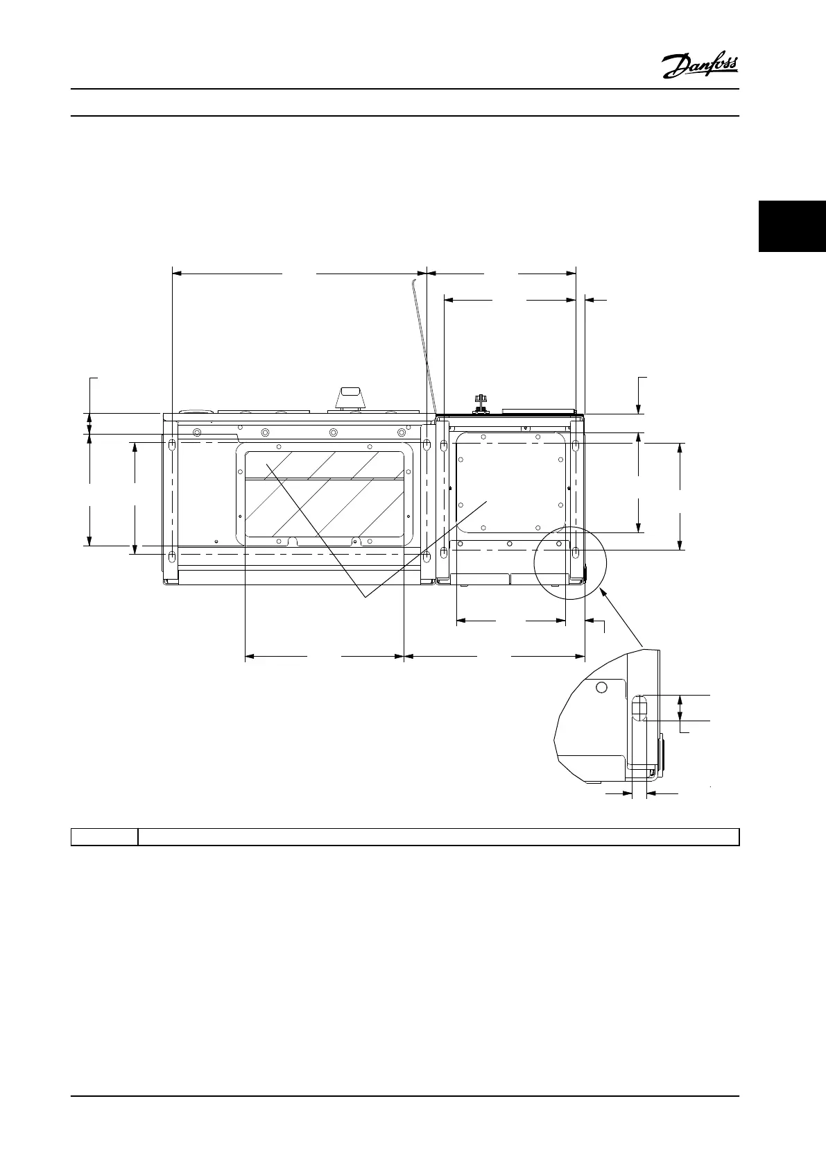
3.3.3 Cable Entry and Anchoring
Cables enter the unit through gland plate openings in the bottom. Figure 3.9, Figure 3.10, Figure 3.11, and Figure 3.12 show
gland entry locations and detailed views of anchoring hole dimensions.
Bottom View, D1n/D2n
64.5
[2.5]
20.0
[0.8]
40.0
[1.6]
560.0
[22.0]
327.4
[12.9]
289.4
[11.4]
227.8
[9.0]
246.0
[9.7]
350.0
[13.8]
397.3
[15.6]
240.0
[9.4]
220.0
[8.7]
235.0
[9.3]
42.3
[1.7]
8X 14.0
[0.6]
8X 25.0
[1.0]
1
130BE112.10
1 Cable entry locations
Figure 3.9 Cable Entry Diagram, Enclsoure Size D1n
Installation Installation Manual
MG37A322 Danfoss A/S © Rev. 04/2015 All rights reserved. 25
3 3

 Loading...


