up/ down is activated for less than 400 ms the
resulting reference will be increased/ decreased by
0.1 %. If Speed up/ down is activated for more
than 400 ms the resulting reference will follow the
setting in ramping up/ down parameter 3-x1/ 3-x2.
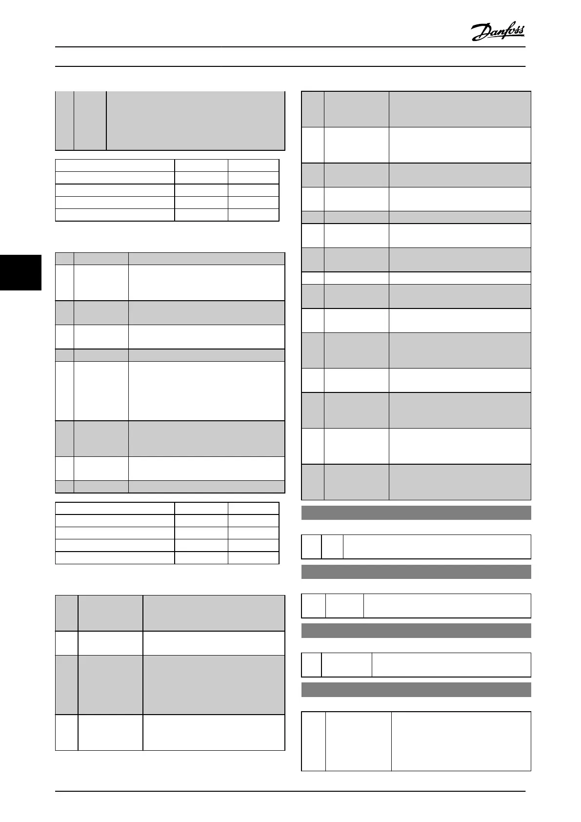
Shut down Catch up
Unchanged speed 0 0
Reduced by %-value 1 0
Increased by %-value 0 1
Reduced by %-value 1 1
Table 6.6
[22] Speed down Same as Speed up [21].
[23] Set-up select
bit 0
Select Set-up select bit 0 or Select Set-up
select bit 1 to select one of the four set-ups.
Set 0-10 Active Set-up to Multi Set-up.
[24] Set-up select
bit 1
(Default Digital input 32): Same as [23] Set-
up select bit 0.
[28] Catch up Increases or reduces reference value set in
3-12 Catch up/slow Down Value.
[29] Slow down
[28] Same as Catch up.
[30] Counter input
Precise stop function in 1-83 Precise Stop
Function acts as Counter stop or speed
compensated counter stop with or without
reset. The counter value must be set in
1-84 Precise Stop Counter Value.
[32] Pulse input Use pulse sequence as either reference or
feedback. Scaling is done in parameter
group 5-5* Pulse Input.
[34] Ramp bit 0 Enables a choice between one of the 4
ramps available, according to Table 6.7.
[35] Ramp bit 1
Same as [34] Ramp bit 0.
Preset ramp bit 1 0
Ramp 1 0 0
Ramp 2 0 1
Ramp 3 1 0
Ramp 4 1 1
Table 6.7
[36]
Mains failure
inverse
Activates 14-10 Mains Failure. Mains
failure inverse is active in the Logic .0.
situation.
[39] Day/Night
Control
Reduce the max. frequency with the
setting in 28-74 Night Speed Drop [RPM].
[41] Latched Precise
Stop inverse
Sends a latched stop signal when the
precise stop function is activated in
1-83 Precise Stop Function. The Latched
Precise stop inverse function is available
for terminals 18 or 19.
[55] DigiPot Increase INCREASE signal to the Digital Potenti-
ometer function described in parameter
group 3-9* Digital Potmeter.
[56] DigiPot Decrease DECREASE signal to the Digital Potenti-
ometer function described in parameter
group 3-9* Digital Potmeter
[57] DigiPot Clear Clears the Digital Potentiometer
reference described in parameter group
3-9* Digital Potmeter
[60] Counter A (Terminal 29 or 33 only) Input for
increment counting in the SLC counter.
[61] Counter A (Terminal 29 or 33 only) Input for
decrement counting in the SLC counter.
[62] Reset Counter A Input for reset of counter A.
[63] Counter B (Terminal 29 or 33 only) Input for
increment counting in the SLC counter.
[64] Counter B (Terminal 29 or 33 only) Input for
decrement counting in the SLC counter.
[65] Reset Counter B Input for reset of counter B.
[70] Mech. Brake
Feedback
Brake feedback for hoisting applications
[71] Mech. Brake
Feedback inv.
Inverted brake feedback for hoisting
applications
[80] PTC Card 1
All Digital Inputs can be set to [80] PTC
Card 1. However, only one Digital Input
must be set to this choice.
[121] Lead Pump
Alternation
[130] Compressor
Interlock
Use with cascade controller. Logic 1 will
stop the fixed speed compressor and
give a warning
[131] Compressor
Interlock
Use with cascade controller. Logic 1 will
stop the fixed speed compressor and
give a warning
[132] Compressor
Interlock
Use with cascade controller. Logic 1 will
stop the fixed speed compressor and
give a warning
5-10 Terminal 18 Digital Input
Option: Function:
[8] * Start
Functions are described under parameter group 5-1*
Digital Inputs
5-11 Terminal 19 Digital Input
Option: Function:
[10] * Reversing Functions are described under parameter group
5-1* Digital Inputs
5-12 Terminal 27 Digital Input
Option: Function:
[2] * Coast inverse Functions are described under parameter
group 5-1* Digital Inputs
5-13 Terminal 29 Digital Input
Option: Function:
Select the function from the available
digital input range and the additional
options [60], [61], [63] and [64].
Counters are used in Smart Logic
Control functions.
Parameter Descriptions
Operating Instructions VLT
®
CDS302 and CDS303
62 MG34M302 - VLT
®
is a registered Danfoss trademark/Commercial Compressor
6
6