Pin
No.
Schematic
acronym
Function Description Reading using a
digital voltmeter
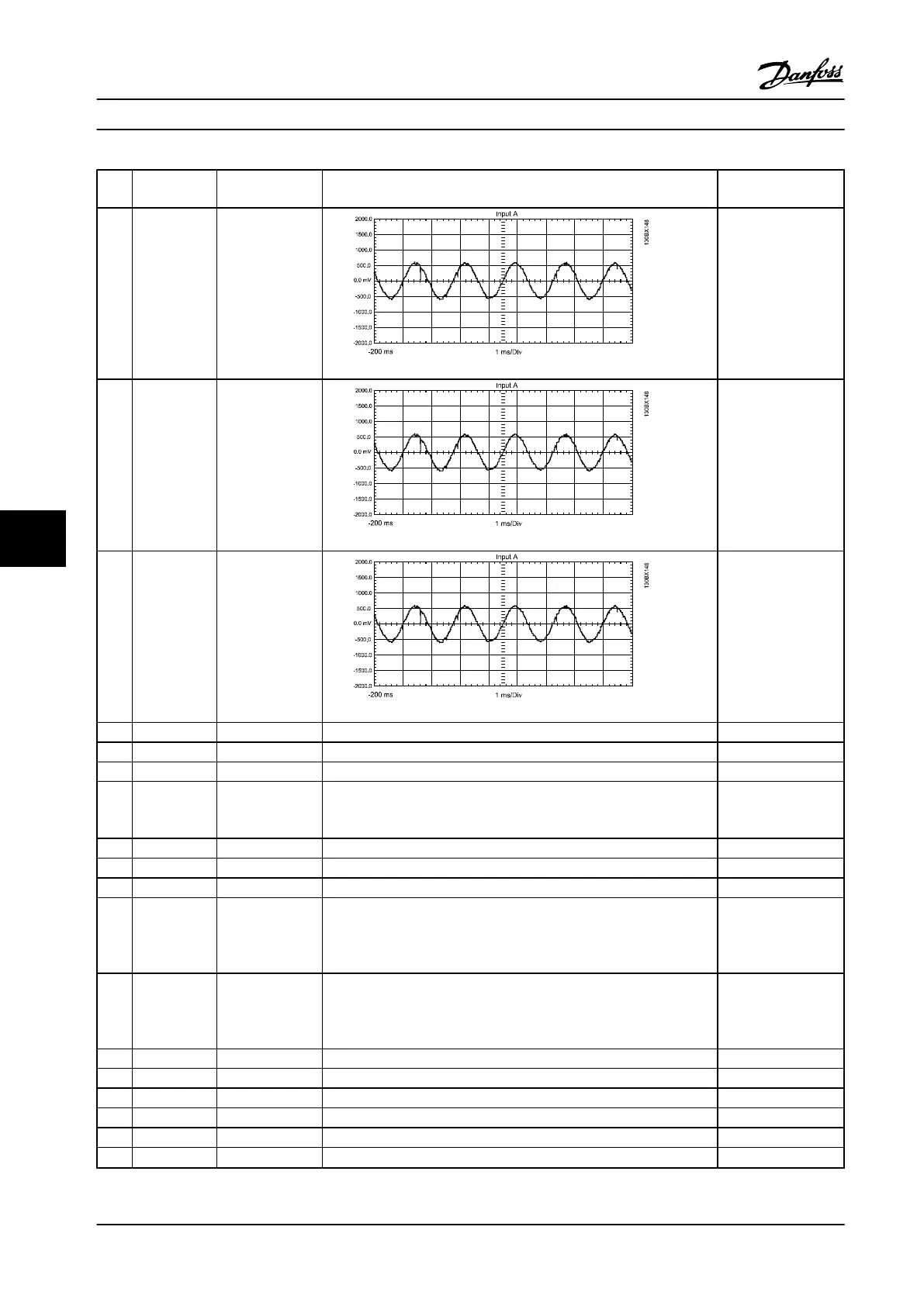
1 IU1 Current sensed,
U phase, not
conditioned
Approx 400 mV RMS @100% load
.937 VACpeak @
165% of CT current
rating. AC waveform
@ output frequency
of the filter.
2 IV1 Current sensed,
V phase, not
conditioned
Approx 400 mV RMS @100% load
.937 VACpeak @
165% of CT current
rating. AC waveform
@ output frequency
of the filter.
3 IW1 Current sensed,
W phase, not
conditioned
Approx 400 mV RMS @100% load
.937 VACpeak @
165% of CT current
rating. AC waveform
@ output frequency
of the filter.
4 COMMON Logic common This common is for all signals.
5 Not used
6 Not used
7 INRUSH Control Card
signal
Signal from the control card to start gating the SCR front end 3.3 V DC – Inrush
mode 0 V DC – Run
mode
8 Not used
9 Not used
10 Not used
11 VPOS (+)18 V DC
regulated supply
(+)16.5 to 19.5 V
DC
The red LED indicates voltage is present between VPOS and VNEG
terminals.
(+)18 V DC regulated
supply (+)16.5 to 19.5
V DC
12 VNEG (-) 18 V DC
regulated supply
(-) 16.5 to 19.5 V
DC
The red LED indicates voltage is present between VPOS and VNEG
terminals.
(-)18 V DC regulated
supply
(-)16.5 to 19.5 V DC
13 Not used
14 Not used
15 Not used
16 Not used
17 Not used
18 Not used
Special Test Equipment Service Manual
122 Danfoss A/S © Rev. 2014-02-10 All rights reserved. MG94A222
88
 Loading...


