Start delay
In 1-71 Start Delay, a delay starting time was
set. A start command is activated and the
motor will start after the start delay time
expires.
Start fwd/rev Start forward and start reverse were selected
as functions for two different digital inputs
(parameter group 5-1* Digital Inputs). The
motor will start in forward or reverse
depending on which corresponding terminal
is activated.
Stop The adjustable frequency drive has received a
stop command from the LCP, digital input or
serial communication.
Trip An alarm occurred and the motor is stopped.
Once the cause of the alarm is cleared, the
adjustable frequency drive can be reset
manually by pressing [Reset] or remotely by
control terminals or serial communication.
Trip lock An alarm occurred and the motor is stopped.
Once the cause of the alarm is cleared, power
must be cycled to the adjustable frequency
drive. The adjustable frequency drive can then
be reset manually by pressing [Reset] or
remotely by control terminals or serial
communication.
Table 2.4 Operation Status
NOTICE!
In auto/remote mode, the adjustable frequency drive
requires external commands to execute functions.
2.5 Service Functions
Service information for the adjustable frequency drive is on
display lines 3 and 4. Included in the data are counters
that tabulate operating hours, power-ups, and trips; fault
logs of status values during the 20 most recent events that
stopped the adjustable frequency drive; and adjustable
frequency drive nameplate data. The service information is
accessed by displaying items in parameter group 15-**
Drive Information
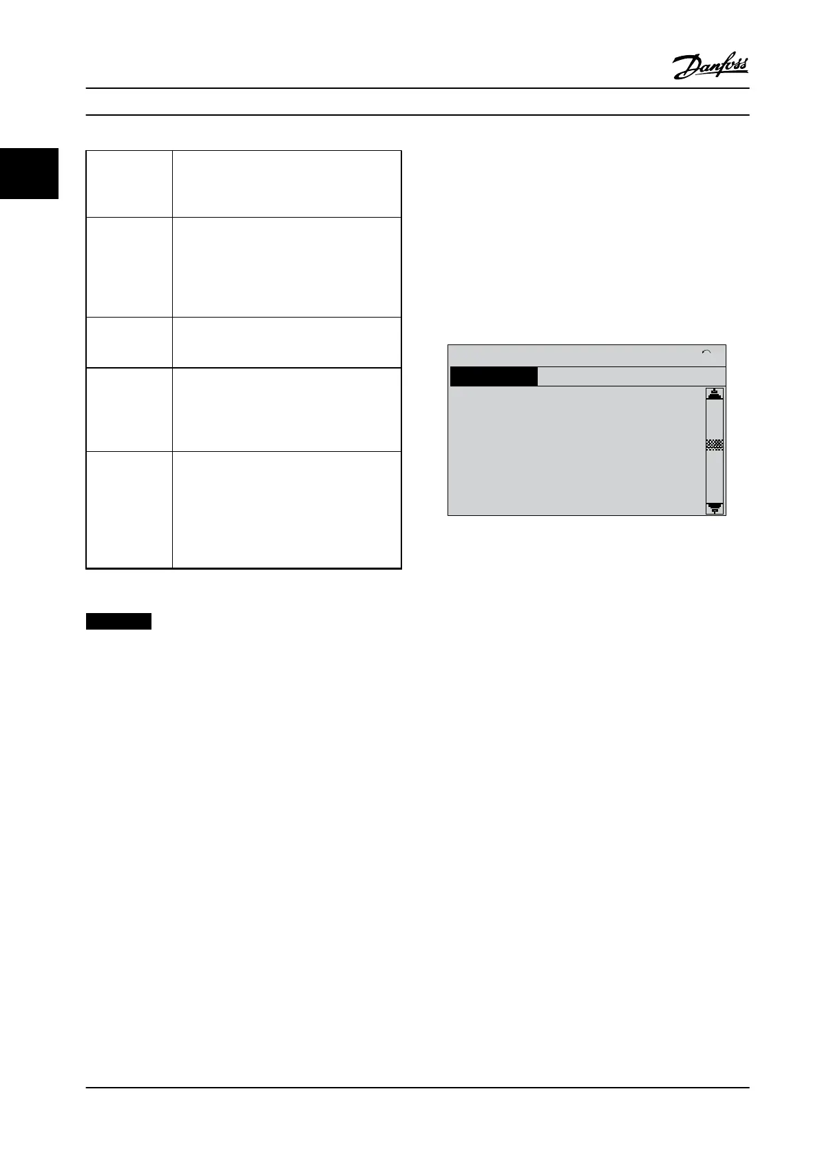
130BC283.10
Operating Data
15-04 Over Temp’s
0
1(1)
15-0
4.2% 0.81A
*
Figure 2.14 Parameter Group 15 Menu
See the Programming Guide for detailed information on
accessing and displaying parameters and for descriptions
and procedures for service information available in
parameter group 15-** Drive Information
2.6
Adjustable Frequency Drive Inputs and
Outputs
The adjustable frequency drive operates by receiving
control input signals. The adjustable frequency drive can
also output status data or control auxiliary devices. Control
input is connected to the adjustable frequency drive in
three possible ways. One way for adjustable frequency
drive control is through the LCP on the front of the
adjustable frequency drive when operating in local (hand)
mode. These inputs include start, stop, reset, and speed
reference.
Another control source is through serial communication
from a serial bus. A serial communication protocol supplies
commands and references to the adjustable frequency
drive, can program the adjustable frequency drive, and
reads status data from the adjustable frequency drive. The
serial bus connects to the adjustable frequency drive
through the RS 485 serial port or through a communi-
cation option card.
Operator Interface and Adju...
Service Manual
28 Danfoss A/S © Rev. 2014-02-10 All rights reserved. MG94A222
22

 Loading...


