Number Description Warning Alarm/
Trip
Alarm/
Trip Lock
Parameter
Reference
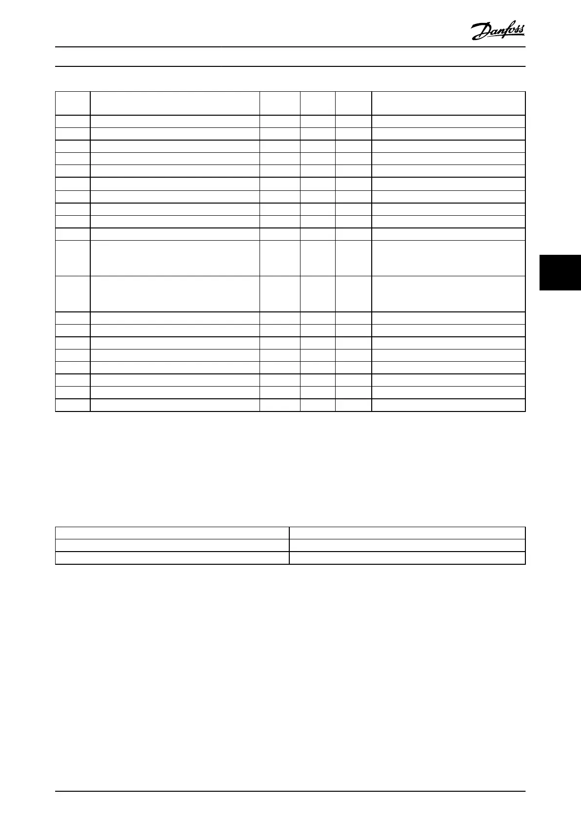
91 Analog input 54 wrong settings – – X S202
99 Locked rotor – X X –
101 Speed monitor X X –
104 Mixing fans X X – –
122 Mot. rotat. unexp. – X – –
123 Motor mod. changed – X – –
163 ATEX ETR cur.lim.warning X – –
164 ATEX ETR cur.lim.alarm – X – –
165 ATEX ETR freq.lim.warning X – –
166 ATEX ETR freq.lim.alarm – X – –
210 Position tracking X X – Parameter 4-70 Position Error Function,
parameter 4-71 Maximum Position Error,
parameter 4-72 Position Error Timeout
211 Position limit X X – Parameter 3-06 Minimum Position,
parameter 3-07 Maximum Position,
parameter 4-73 Position Limit Function
212 Homing not done – X – Parameter 17-80 Homing Function
213 Homing timeout – X – Parameter 17-85 Homing Timout
214 No sensor input – X – –
220 Conguration File Version not supported X – – –
246 Pwr.card supply – – X –
250 New spare part – – X –
251 New type code – X X –
430 PWM Disabled – X – –
Table 6.4 Alarm/Warning Code List
(X) Dependent on parameter.
1) Cannot be auto reset via parameter 14-20 Reset Mode.
A trip is the action following an alarm. The trip coasts the motor and is reset by pressing [Reset] or by a digital input
(parameter group 5-1* Digital Inputs). The original event that caused an alarm cannot damage the frequency converter or
cause dangerous conditions. A trip lock is an action when an alarm occurs, which could damage the frequency converter or
connected parts. A trip lock situation can only be reset by a power cycling.
Warning Yellow
Alarm Flashing red
Trip locked Yellow and red
Table 6.5 Indicator Light
Maintenance, Diagnostics, a... User Guide
MG37L202 Danfoss A/S © 08/2017 All rights reserved. 37
6
6
 Loading...


