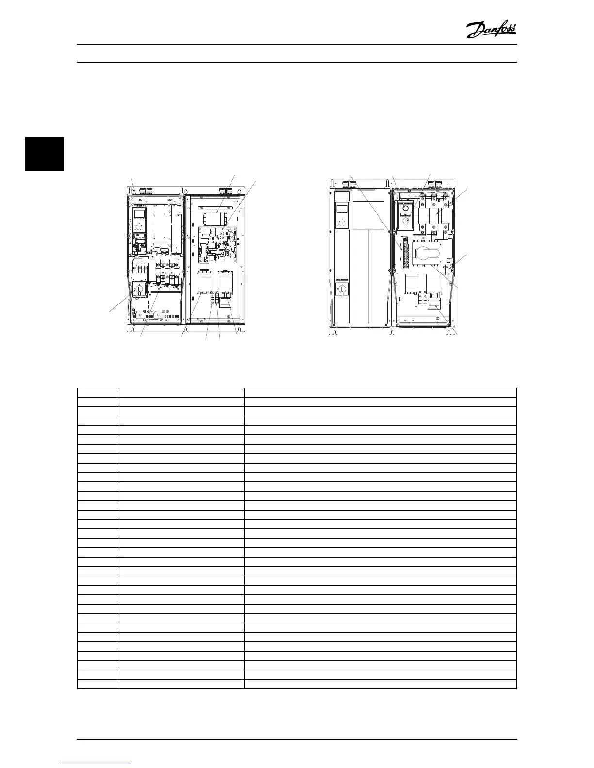
Illustration 3.8 Sample Mechanical Layout Diagram
ID Definition Function
24 V Option panel 24 V DC SMPS Supply 24 V DC control power to option panel for internal use only
CB1 Main Circuit breaker Provide isolation between option panel and current protection for incoming mains
DS1 Main or line disconnect Provide isolation between option panel and mains
DS2 Drive disconnect Provide isolation between VFD and line voltage
DF15 Main fused disconnect Provide isolation between option panel and mains
DV1 VFD output motor filter Output filter to provide filtering for PWM drive output wave form
F12 T1 secondary fuse Current protection for internal 120 V AC control circuit
F13 T1 primary fuse Current protection for line side of 120 V AC internal control transformer
F15 Line or main fuse Provide current protection to option panel
F16 Drive fuse Provide current protection to drive
GD Ground terminal Customer connection for power grounds to mains and motor
LR1 VFD input line reactor Input reactor to provide additional input impeadance to drive
M1 VFD input contactor Provide isolation between VFD and line voltage
M2 VFD output contactor Provide isolation between VFD and motor
M3 Bypass contactor Provide line voltage to motor
M4 Motor 1 contactor Used to select motor 1 operation
M5 Motor 2 contractor Used to select motor 2 operation
MT1 Motor 1 connection terminal Provides termination point for motor leads in option panel
OL1 Overload for motor 1 Provide overload protection to motor when running in bypass
OL2 Overload for motor 2 Provide overload protection to motor when running in bypass
PL2 Bypass indicator light Provides indication when motor is in bypass mode
S1 Bypass selector switch Operator interface for bypass mode selection on electromechanical bypass
S103 Auto bypass selection switch 4 position switch used to setup auto bypass on EMB2 control option
S2 CMS selector switch Operator interface for contactor motor selection
T1 120 V AC control transformer Provide internal 120 V AC supply
T3 120 V AC control transformer Provide customer 120 V AC supply
TB1 Terminal Block 1 Customer bypass control connections for ECB-CMS and EMB0 control option
VFD Variable frequency drive Provide variable frequency and voltage to AC motor
X55 Customer terminal block Customer control connection terminal block on EMB1 and EMB2 control option
X56 Customer terminal block Customer control connection terminal block on EMB1 and EMB2 control option
X58 Customer terminal block Customer control connection terminal block on EMB2 control option
Table 3.3 Reference Designator Definitions
Installation Option Panel Operating Instructions
16 MG14I102 - VLT
®
is a registered Danfoss trademark
3
3

 Loading...


