4.1.1 Inspection Before Start Up
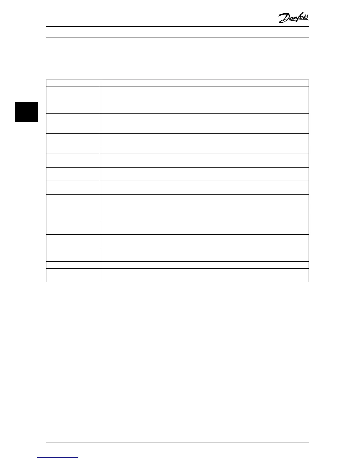
Before applying power to the unit, inspect the entire installation as detailed in Table 4.1.
Inspect for Description
Auxiliary equipment Look for auxiliary equipment, switches, disconnects, or input fuses/circuit breakers that may reside on input
power side of drive or output side to motor. Examine their operational readiness and ensure they are ready
in all respects for operation at full speed. Check function and installation of pressure sensors or encoders
(etc.) used for feedback to drive. Remove power factor correction caps on motor(s), if present.
Cable routing Ensure that input power, motor wiring and control wiring are in three separate metallic conduits for high
frequency noise isolation. Failure to isolate power, motor and control wiring could result in less than
optimum drive and associated equipment performance.
Control wiring Check for broken or damaged wires and connections. Check the voltage source of the signals, if necessary.
The use of shielded cable or twisted pair is recommended. Ensure the shield is terminated correctly.
EMC considerations Check for proper installation with regard to electromagnetic capability.
Environmental conditions See option panel label for the maximum ambient operating temperature. Humidity levels must be less than
95% non-condensing.
Fan clearance Some units have a cooling fan located below the drive and require sufficient clearance for fan removal. See
the installation drawing supplied with the unit for clearance requirements.
Fusing and circuit breakers Check that all fuses are inserted firmly and in operational condition and that all circuit breakers are in the
open position.
Grounding The option panel requires a dedicated ground wire from its chassis to the building ground. It is highly
recommended that the motor be grounded to the panel chassis. The use of conduit or mounting of the
panel to a metal surface is not considered a suitable ground. Check for good ground connections that are
tight and free of oxidation.
Input and output power
wiring
Check for loose connections. Check for proper fusing or circuit breakers.
Panel interior Option panel interior must be free of dirt, metal chips, moisture, and corrosion. Check for harmful airborne
contaminates such as sulfur based compounds.
Proper clearance Option panels require top and bottom clearance adequate to ensure proper air flow for cooling in
accordance with the unit size.
Switches Ensure that all switch and disconnect settings are in the proper position.
Vibration Look for any unusual amount of vibration the equipment may be subjected to. The panel should be
mounted solidly or the use of shock mounts employed.
Table 4.1 Inspection Before Start Up
Start Up Option Panel Operating Instructions
30 MG14I102 - VLT
®
is a registered Danfoss trademark
44

 Loading...


