1.5 Switch Mode Power Supply (SMPS)
The VFD’s logic circuitry is backed up by an independent
panel-mounted switch mode power supply so that, even if
the drive loses power, the control and communication
functions are maintained. The SMPS converts three-phase
AC input power to 24 VDC control power. Since the SMPS
draws power from all three phases, it offers immunity
protection from most phase-loss and brown-out
conditions. The SMPS is internally protected from short
circuit on its output and three board-mounted fuses
provide additional protection. The SMPS is not designed
for external use and may take up to 5 s to initialize at
power-up.
1.6 Disconnects
1.6.1 Main Disconnect
The main disconnect removes line input power to the
drive and bypass. A main disconnect is available in four
options.
•
Fused disconnect
two-position (ON/OFF) rotary switch, padlock
compatible, with three fuses, one on each phase,
built into the switch. For safety, the switch must
be in the OFF position before the option panel
door can be opened
•
Disconnect with fuses
Two-position (ON/OFF) rotary switch, padlock
compatible, with a fuse block mounted separately
from the disconnect. Three fuses, one on each
phase, are located on the fuse block. For safety,
the switch must be in the OFF position before
the option panel door can be opened.
•
Disconnect without fuses
For user-supplied fuses option.
•
Main circuit breaker
A thermal/ magnetic current interrupt device
using an ON/TRIP/OFF/RESET switch. When in the
ON position, a trip fault removes power from the
drive/bypass circuit and the switch moves to the
TRIP setting. It must be moved to the RESET
position momentarily after the fault has been
cleared to reset the circuit breaker.
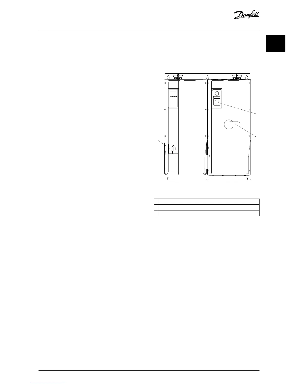
1.6.2
Drive Disconnect (Optional)
Two-position (ON/OFF) rotary switch disconnects main AC
line input power to the drive only.
1.6.3
Bypass Selector Switch
The bypass selector switch is used for either the 2-
contactor or 3-contactor bypass for EMB units.

 Loading...


