3.4.2 Wire and Cable Access
•
Determine the wiring path through the option
panel enclosure. See the mechanical layout
drawing located on the inside cover of the unit
for locations to connect power and motor wiring.
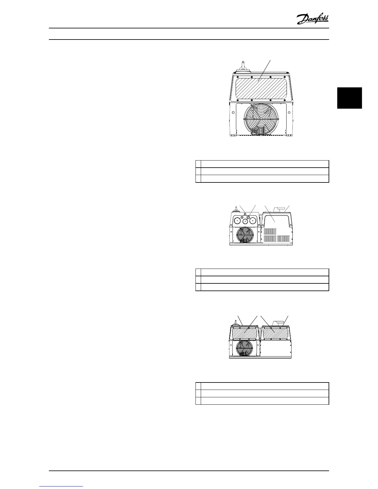
•
Removable access covers are provided for cable
connections (see figure Conduit Entry Diagrams).
Remove access covers before drilling holes to
prevent metal shavings from damaging internal
electronic components.
•
For some units, access holes are provided for
input power, motor leads, and control wiring.
•
Run input power, motor wiring, and control
wiring in three separate conduits for isolation.
NOTE
RUN INPUT POWER, MOTOR WIRING AND CONTROL
WIRING IN THREE SEPARATE METALLIC CONDUITS OR
RACEWAYS FOR HIGH FREQUENCY NOISE ISOLATION.
FAILURE TO ISOLATE POWER, MOTOR AND CONTROL
WIRING COULD RESULT IN LESS THAN OPTIMUM DRIVE
AND ASSOCIATED EQUIPMENT PERFORMANCE.
•
The drive always resides in the left-hand panel
when multiple panels are present.
•
Power connections are typically on the rightside
panel, or far right for tier 3 panel configurations.
•
NEMA 12 enclosures available for additional
environmental protection.
•
Control wiring should be isolated from power
components inside the unit as much as possible.
•
See the mechanical layout drawing on the inside
of the unit’s panel and the connection diagram
supplied with the unit for connection details.

 Loading...


