5.1.1 EMB(0) and EMB1
The electromechanical bypass is available in two additional types, the EMB(0) and EMB1. Each has reduced functionality
from the EMB2. The figures and tables below list for features and functions available in either type. Table 5.7, Table 5.8 and
Table 5.9 list terminal functions for EMB(0) and EMB1, respectively, and EMB1 default parameter settings for bypass
operation. If the drive is reinitialized, be sure that these settings are maintained or reset for proper bypass operation.
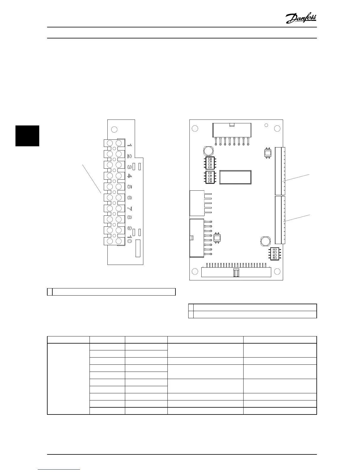
See the mechanical layout diagram inside the cover of the unit for connector locations within the unit.
Illustration 5.4 EMB1 Control Card
1
Terminal X55
2 Terminal X56
Table 5.6 Legend to Illustration 5.4
Conn.
Term. Input/Output Type Function
TB1
1 Input Normally closed, dry relay contact Safety input, open to stop
2 Input
3 Common Not for customer use Not for customer use
4 Output Normally open, dry aux contact Closed when panel is in drive mode
5 Output
6 Output Normally open, dry aux contact Closed when panel is in Bypass
Mode
7 Output
8 Input Normally open, dry contact CMS Motor 1, close to select
9 CMS Common Normally open, dry contact CMS common
10 Input Normally open, dry contact CMS Motor 2, close to select
Table 5.7 EMB(0) Terminal Functions
Electromechanical Bypass (E... Option Panel Operating Instructions
36 MG14I102 - VLT
®
is a registered Danfoss trademark
55

 Loading...


