For a detailed description of the DP-V1 command
handling, refer to the PROFIBUS DP-V1 Design Guide.
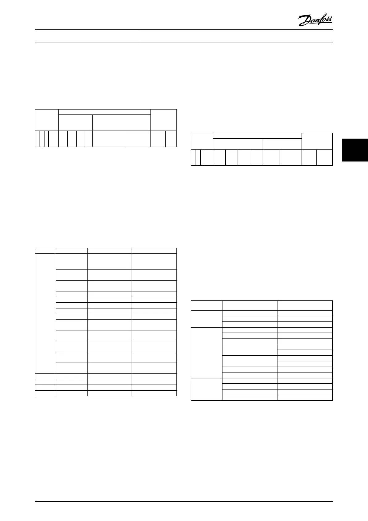
Example
Slot=0
Index=47
PROFIBUS
telegram
header
Data unit PROFIBUS-
telegram
trailer
DP-V1
Command/
response
PROFIdrive V3.0 parameter
channel
DU
0
DU
1
D
U
2
D
U
3
Req./Res.
Header
Data
Table 5.3 General Structure for Telegram
Use the DP-V1 command/response part for the standard
DP-V1 read/write on slot 0, index 47 data block.
Use the PROFIdrive V3 parameter channel to access
specific parameter data in the frequency converter.
5.2.7
DP-V1 Read/Write Services
Table 5.4 shows the content of the DP-V1 command/
Response headers and their possible attributes.
DU byte
Value Meaning Specified
0 Function
number
0x48
Idle REQ, RES
0x51 Data transport REQ,
RES
0x56 Resource manager
REQ
0x57 Initiate REQ, RES
0x58 Abort REQ
0x5C Alarm REQ, RES
0x5E Read REQ, RES
0x5F Write REQ, RES
0xD1 Data transport
negative response
0xD7 Initiate negative
response
0xDC Alarm negative
response
0xDE Read negative
response
0xDF Write negative
response
1 Always zero Slot number DPV1
2 47 Index DPV1
3 xx Data length DPV1
4..n User data PNO drive profile V3.0
Table 5.4 DP-V1 Command/Response Headers
5.2.8
DP-V1 Acyclical Parameter Channel
Use the PROFIdrive parameter channel for read and write
access to parameter values and attributes.
•
Parameter values of simple variable, array and
visible string.
•
Parameter description elements such as type,
minimum/maximum value, and so on.
•
Descriptive text for parameter values.
•
Access to multiple parameters in one telegram is
also possible.
Table 5.5 shows the structure of the PROFIdrive parameter
channel.
PROFIBUS DP-V1 telegram for read/write from or to a
frequency converter parameter:
PROFIBUS
telegram
header
Data unit PROFIBUS
telegram
trailer
DP-V1
command/response
PROFIdrive V3.0
parameter channel
DU
0
DU
1
DU
2
DU
3
Req./
Res.
Header
Data
Table 5.5 Structure of the PROFIdrive Parameter Channel
Table 5.6 shows the principle structure of the PROFIdrive
parameter channel.
The DP-V1 parameter request telegram consists of 3 data
blocks:
•
A request header, which defines the request (read
or write), and the number of parameters to
access. The master sets the request reference, and
uses this information to evaluate the response.
•
An address field, where all addressing attributes
of the desired parameters are defined.
•
A data field, where all parameter data values are
placed.
DP-V1
Parameter request Byte no.
Request
header
Request reference 0
Request ID 1
Axis 2
Address field No. of parameters 3
Attribute 4
No. of elements 5
Parameter no. 6
7
Sub index 8
9
n'th parameter no. 4+6*(n-1)
...
Data field Data format 4+6*n
No. of values (4+6*n)+1
Values (4+6*n)+2
n'th data value ...
Table 5.6 Principle Structure of the PROFIdrive Parameter Channel
The DP-V1 parameter response telegram consists of 2 data
blocks:
•
A response header, which indicates if the request
is performed without errors (response ID), the
number of parameters, and the request reference
Parameter Access
Programming Guide
MG37G102 Danfoss A/S © Rev. 05/2014 All rights reserved. 25
5 5

 Loading...


