•
How to use PPO type 1 to change the ramp-up
time to 10 s, in3-41 Ramp 1 Ramp Up Time.
•
How to command a start and speed reference of
50%.
Frequency converter parameter settings:
8-50 Coasting Select: Bus
Parameter 8-10 Control Word Profile: PROFIdrive profile
5.3.5.1 PCV
PCA parameter characteristics
PCA part (byte 1-2).
The RC part tells what the PCV part must be used for. The
functions available are listed in chapter 5.3.1 PCA Handling.
When a parameter is changed, select value 2 or 3. In this
example, 3 is selected, because 3-41 Ramp 1 Ramp Up Time
covers a long word (32 bits).
3-41 Ramp 1 Ramp Up Time=155 hex: In this example, byte
1 and 2 are set to 3155. See the values for bytes 1 and 2
in Table 5.18.
IND (bytes 3-4)
Used when reading/changing parameters with sub-index,
for example parameter 9-15 PCD Write Configuration. In the
example bytes 3 and 4 are set to 00 hex. See the values
for bytes 3 and 4 in Table 5.18.
PVA (bytes 5-8)
The data value of 3-41 Ramp 1 Ramp Up Time must be
changed to 10.00 s. The value transmitted must be 1000,
because the conversion index for 3-41 Ramp 1 Ramp Up
Time is 2. This means that the value received by the
frequency converter is divided by 100, such that the
frequency converter perceives 1000 as 10.00. Bytes
5-8=1000=03E8 hex. See chapter 5.4 PROFIBUS DP
Parameter and Data Type. See the values for bytes 5-8 in
Table 5.18.
5.3.5.2
PCD
Control word (CTW) according to PROFIdrive profile:
Control words consist of 16 bits. The meaning of each bit
is explained in chapter 4.4.1 Control Word according to
PROFIdrive Profile (CTW) and chapter 4.4.2 Status Word
according to PROFIdrive Profile (STW). The following bit
pattern sets all necessary start commands:
0000 0100 0111 1111=047F hex.*
0000 0100 0111 1110=047E hex.*
0000 0100 0111 1111=047F hex. These are the values for
bytes 9 and 10 in Table 5.18.
Quick stop: 0000 0100 0110 1111=046F hex.
Stop: 0000 0100 0011 1111=043F hex.
NOTICE
* For restart after power up:
•
Set bits 1 and 2 of the CTW to 1.
•
Toggle bit 0 from 0 to 1.
5.3.5.3 MRV
MRV is the speed reference, with data format Standardised
value. 0 hex=0% and 4000 hex=100%.
In the example, 2000 hex is used, corresponding to 50% of
maximum frequency in 3-03 Maximum Reference. See the
values for bytes 11 and 12 in Table 5.18.
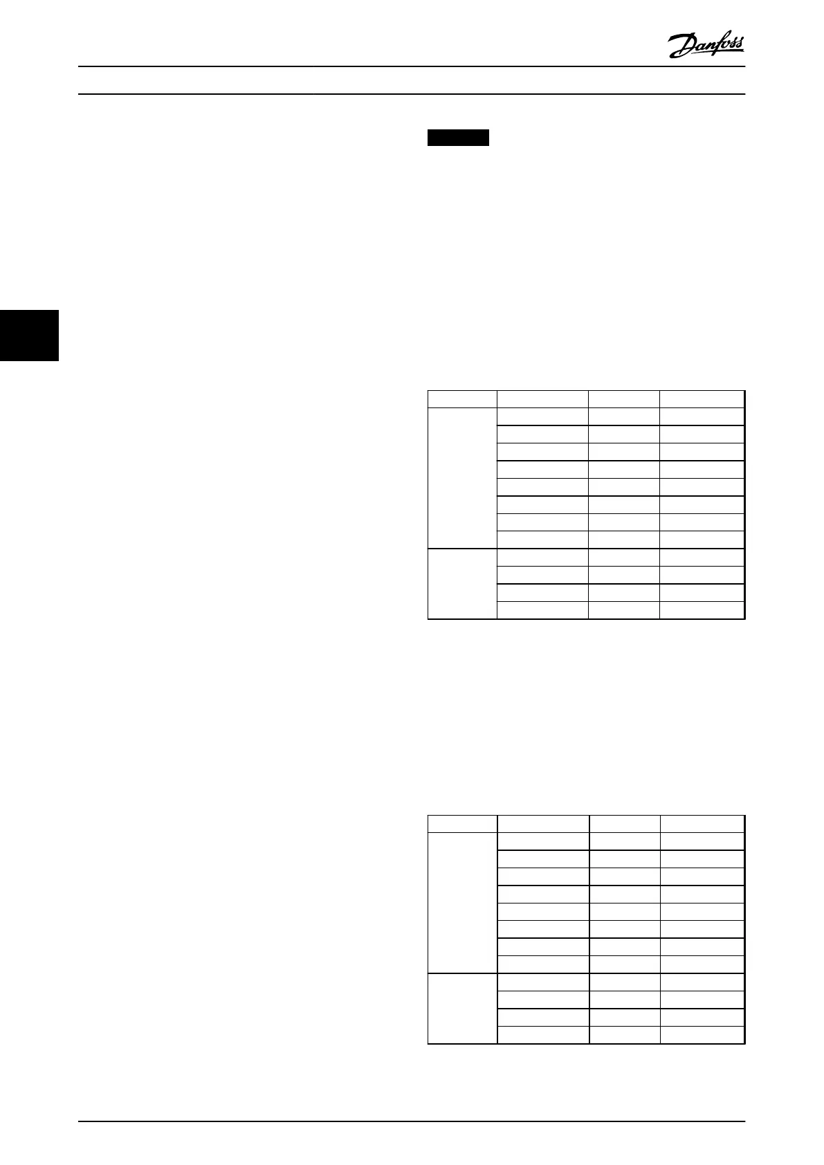
The whole PPO therefore has the following values in hex:
Byte Value
PCV
PCA 1 31
PCA 2 55
IND 3 00
IND 4 00
PVA 5 00
PVA 6 00
PVA 7 03
PVA 8 E8
PCD
CTW 9 04
CTW 10 7F
MRV 11 20
MVR 12 00
Table 5.18 Request Example: PPO Values in Hex
The process data within the PCD part acts immediately
upon the frequency converter, and can be updated from
the master as quickly as possible. The PCV part is a
"handshake" procedure, which means that the frequency
converter has to acknowledge the command, before a new
one can be written.
Table 5.18 shows a positive response to the request
example from Table 5.18.
Byte Value
PCV
PCA 1 21
PCA 2 55
IND 3 00
IND 4 00
PVA 5 00
PVA 6 00
PVA 7 03
PVA 8 E8
PCD
STW 9 0F
STW 10 07
MAV 11 20
MAR 12 00
Table 5.19 Response Example: Positive Response
Parameter Access
Programming Guide
30 Danfoss A/S © Rev. 05/2014 All rights reserved. MG37G102
55

 Loading...


