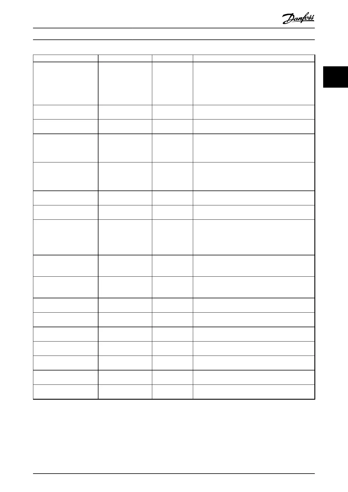
Parameter Option Default Usage
Parameter 1-73 Flying Start [0] Disabled
[1] Enabled
[0] Disabled Select [1] Enabled to enable the frequency converter to
catch a motor spinning due to mains drop-out. Select [0]
Disabled if this function is not required. When this
parameter is set to [1] Enabled, parameter 1-71 Start Delay
and parameter 1-72 Start Function are not functional.
Parameter 1-73 Flying Start is active in VVC
+
mode only.
Parameter 3-02 Minimum
Reference
-4999.000–4999.000 0 The minimum reference is the lowest value obtainable by
summing all references.
Parameter 3-03 Maximum
Reference
-4999.000–4999.000 50 The maximum reference is the highest value obtainable by
summing all references.
Parameter 3-41 Ramp 1 Ramp
Up Time
0.05–3600.00 s Size related If asynchronous motor is selected, the ramp-up time is
from 0 to rated parameter 1-23 Motor Frequency. If PM
motor is selected, the ramp-up time is from 0 to
parameter 1-25 Motor Nominal Speed.
Parameter 3-42 Ramp 1 Ramp
Down Time
0.05–3600.00 s Size related For asynchronous motors, the ramp-down time is from
rated parameter 1-23 Motor Frequency to 0. For PM motors,
the ramp-down time is from parameter 1-25 Motor Nominal
Speed to 0.
Parameter 4-12 Motor Speed
Low Limit [Hz]
0.0–400.0 Hz 0 Hz Enter the minimum limit for low speed.
Parameter 4-14 Motor Speed
High Limit [Hz]
0.0–400.0 Hz 100 Hz Enter the maximum limit for high speed.
Parameter 4-19 Max Output
Frequency
0.0–400.0 Hz 100 Hz Enter the maximum output frequency value. If
parameter 4-19 Max Output Frequency is set lower than
parameter 4-14 Motor Speed High Limit [Hz],
parameter 4-14 Motor Speed High Limit [Hz] is set equal to
parameter 4-19 Max Output Frequency automatically.
Parameter 5-40 Function Relay See
parameter 5-40 Function
Relay.
[9] Alarm Select the function to control output relay 1.
Parameter 5-40 Function Relay See
parameter 5-40 Function
Relay.
[5] Drive running Select the function to control output relay 2.
Parameter 6-10 Terminal 53 Low
Voltage
0.00–10.00 V 0.07 V Enter the voltage that corresponds to the low reference
value.
Parameter 6-11 Terminal 53
High Voltage
0.00–10.00 V 10 V Enter the voltage that corresponds to the high reference
value.
Parameter 6-12 Terminal 53 Low
Current
0.00–20.00 mA 4 mA Enter the current that corresponds to the low reference
value.
Parameter 6-13 Terminal 53
High Current
0.00–20.00 mA 20 mA Enter the current that corresponds to the high reference
value.
Parameter 6-19 Terminal 53
mode
[0] Current
[1] Voltage
[1] Voltage Select if terminal 53 is used for current or voltage input.
Parameter 30-22 Locked Rotor
Protection
[0] O
[1] On
[0] O
–
Parameter 30-23 Locked Rotor
Detection Time [s]
0.05–1 s 0.10 s
–
Table 2.4 Set-up Wizard for Open-loop Applications
Programming Programming Guide
MG18B502 Danfoss A/S © 04/2018 All rights reserved. 15
2 2

 Loading...


