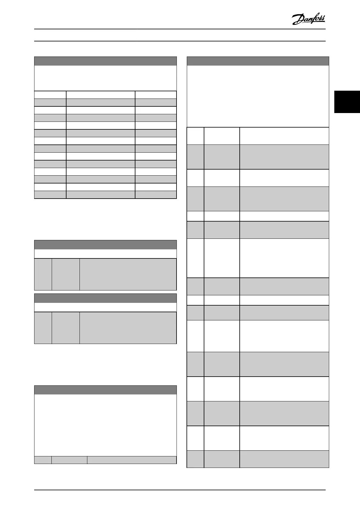
5-13 Terminal 29 Digital Input
Parameter for conguring the input function on input terminal
29.
Option: Function:
[60] Counter A (up)
[61] Counter A (down)
[62] Reset Counter A
[63] Counter B (up)
[64] Counter B (down)
[65] Reset Counter B
[101] Sleep
[120] Lead Pump Start
[121] Lead Pump Alternation
[130] Pump 1 Interlock
[131] Pump 2 Interlock
[132] Pump 3 Interlock
[133] Pump 4 Interlock
[134] Pump 5 Interlock
3.6.3 5-3* Digital Outputs
Parameters for conguring the output functions for the
output terminals.
5-34 On Delay, Digital Output
Range: Function:
0.01 s* [0 - 600 s] Enter the delay time before the digital
output is switched on. The digital output
(terminal 42/45) condition must not be
interrupted during the delay time.
5-35 O Delay, Digital Output
Range: Function:
0.01 s* [0 - 600 s] Enter the delay time before the digital
output is switched o. The digital output
(terminal 42/45) condition must not be
interrupted during the delay time.
3.6.4 5-4* Relays
Parameters for conguring the timing and the output
functions for the relays.
5-40 Function Relay
Array (Relay 1 [0], Relay 2 [1])
Select options to dene the function of the relays.
The selection of each mechanical relay is realized in an array
parameter. When parameter 0-03 Regional Settings is set to [0]
International, the default value is [9] Alarm. When
parameter 0-03 Regional Settings is set to [1] North America, the
default value is [160] No alarm.
Option: Function:
[0] No operation
5-40 Function Relay
Array (Relay 1 [0], Relay 2 [1])
Select options to dene the function of the relays.
The selection of each mechanical relay is realized in an array
parameter. When parameter 0-03 Regional Settings is set to [0]
International, the default value is [9] Alarm. When
parameter 0-03 Regional Settings is set to [1] North America, the
default value is [160] No alarm.
Option: Function:
[1] Control Ready The control board receives supply
voltage.
[2] Drive ready The frequency converter is ready for
operation and applies a supply signal on
the control board.
[3] Drive ready/
remote control
The frequency converter is ready for
operation in auto-on mode.
[4] Standby / no
warning
The frequency converter is ready for
operation. No start or stop command is
given. No warnings are present.
[5] Drive running The motor runs.
[6] Running / no
warning
The motor runs, and no warnings are
present.
[7] Run in
range/no
warning
The motor runs within the programmed
current ranges, see
parameter 4-50 Warning Current Low and
parameter 4-51 Warning Current High. No
warnings are present.
[8] Run on ref/no
warning
The motor runs at reference speed and
with no warnings.
[9] Alarm An alarm activates output.
[10] Alarm or
warning
An alarm or warning activates output.
[12] Out of current
range
The motor current is outside the ranges
set in parameter 4-50 Warning Current
Low and parameter 4-51 Warning Current
High.
[13] Below current,
low
The motor current is lower than the limit
set in parameter 4-50 Warning Current
Low.
[14] Above current,
high
The motor current is higher than the
limit set in parameter 4-51 Warning
Current High.
[16] Below speed,
low
The frequency converter output speed is
lower than the limit set in
parameter 4-40 Warning Freq. Low.
[17] Above speed,
high
The frequency converter output speed is
higher than the limit set in
parameter 4-41 Warning Freq. High.
[19] Below
feedback, low
The feedback is lower than the limit set
in parameter 4-56 Warning Feedback Low.
Parameters Programming Guide
MG18B502 Danfoss A/S © 04/2018 All rights reserved. 51
3 3

 Loading...


