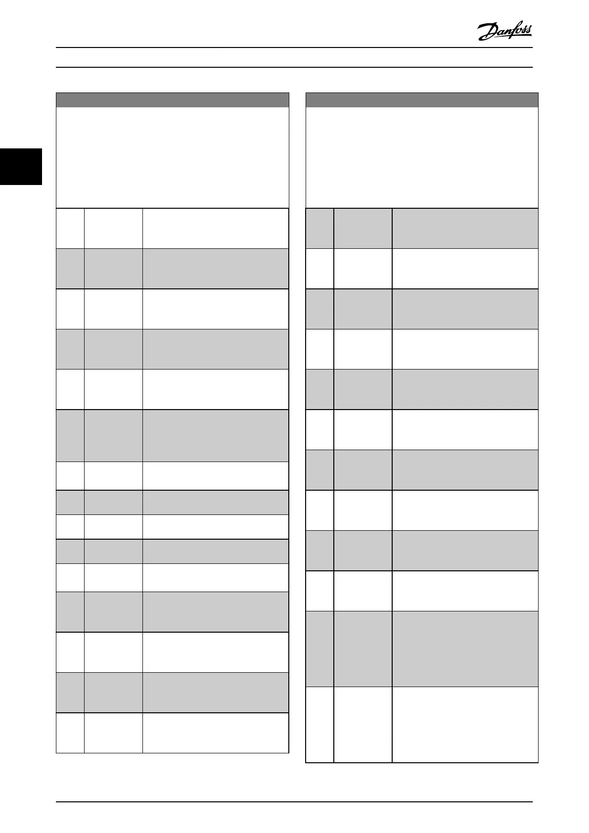
5-40 Function Relay
Array (Relay 1 [0], Relay 2 [1])
Select options to dene the function of the relays.
The selection of each mechanical relay is realized in an array
parameter. When parameter 0-03 Regional Settings is set to [0]
International, the default value is [9] Alarm. When
parameter 0-03 Regional Settings is set to [1] North America, the
default value is [160] No alarm.
Option: Function:
[20] Above
feedback, high
The feedback is higher than the limit set
in parameter 4-57 Warning Feedback
High.
[21] Thermal
warning
The thermal warning turns on when the
temperature exceeds the limit in motor,
frequency converter, or thermistor.
[22] Ready, no
thermal
warning
The frequency converter is ready for
operation and no thermal warning is
present.
[23] Remote, ready,
no thermal
warning
The frequency converter is ready for
operation in auto mode, and no thermal
warning is present.
[24] Ready, Voltage
OK
The frequency converter is ready for
operation and mains voltage is within
the specied voltage range.
[25] Reverse The motor runs/is ready to run clockwise
when logic = 0 and counterclockwise
when logic = 1. Output changes as soon
as reversing signal is applied.
[26] Bus OK Active communication (no timeout) via
serial communication port.
[35] External
Interlock
See digital input.
[36] Control word
bit 11
Bit 11 in control word controls the relay.
[37] Control word
bit 12
Bit 12 in control word controls the relay.
[41] Below
reference, low
The reference is lower than the limit set
in parameter 4-54 Warning Reference Low.
[42] Above ref, high The reference is higher than the limit set
in parameter 4-55 Warning Reference
High.
[45] Bus Control The output is congured in
parameter 5-90 Digital & Relay Bus
Control.
[60] Comparator 0 See parameter group 13-1* Comparators.
If comparator 0 is evaluated as true, the
output goes high. Otherwise, it is low.
[61] Comparator 1 See parameter group 13-1* Comparators.
If comparator 1 is evaluated as true, the
output goes high. Otherwise, it is low.
5-40 Function Relay
Array (Relay 1 [0], Relay 2 [1])
Select options to dene the function of the relays.
The selection of each mechanical relay is realized in an array
parameter. When parameter 0-03 Regional Settings is set to [0]
International, the default value is [9] Alarm. When
parameter 0-03 Regional Settings is set to [1] North America, the
default value is [160] No alarm.
Option: Function:
[62] Comparator 2 See parameter group 13-1* Comparators.
If comparator 2 is evaluated as true, the
output goes high. Otherwise, it is low.
[63] Comparator 3 See parameter group 13-1* Comparators.
If comparator 3 is evaluated as true, the
output goes high. Otherwise, it is low.
[64] Comparator 4 See parameter group 13-1* Comparators.
If comparator 4 is evaluated as true, the
output goes high. Otherwise, it is low.
[65] Comparator 5 See parameter group 13-1* Comparators.
If comparator 5 is evaluated as true, the
output goes high. Otherwise, it is low.
[70] Logic rule 0 See parameter group 13-4* Logic Rules. If
logic rule 0 is evaluated as true, the
output goes high. Otherwise, it is low.
[71] Logic rule 1 See parameter group 13-4* Logic Rules. If
logic rule 1 is evaluated as true, the
output goes high. Otherwise, it is low.
[72] Logic rule 2 See parameter group 13-4* Logic Rules. If
logic rule 2 is evaluated as true, the
output goes high. Otherwise, it is low.
[73] Logic rule 3 See parameter group 13-4* Logic Rules. If
logic rule 3 is evaluated as true, the
output goes high. Otherwise, it is low.
[74] Logic rule 4 See parameter group 13-4* Logic Rules. If
logic rule 4 is evaluated as true, the
output goes high. Otherwise, it is low.
[75] Logic rule 5 See parameter group 13-4* Logic Rules. If
logic rule 5 is evaluated as true, the
output goes high. Otherwise, it is low.
[80] SL digital
output A
See parameter 13-52 SL Controller Action.
The input goes high whenever the smart
logic action [38] Set dig. out. A high is
executed. The input goes low whenever
the smart logic [32] Action Set dig. out. A
low is executed.
[81] SL digital
output B
See parameter 13-52 SL Controller Action.
The input goes high whenever the smart
logic action [39] Set dig. out. B high is
executed. The input goes low whenever
the smart logic [33] Action Set dig. out. B
low is executed.
Parameters
VLT
®
HVAC Basic Drive FC 101
52 Danfoss A/S © 04/2018 All rights reserved. MG18B502
33

 Loading...


