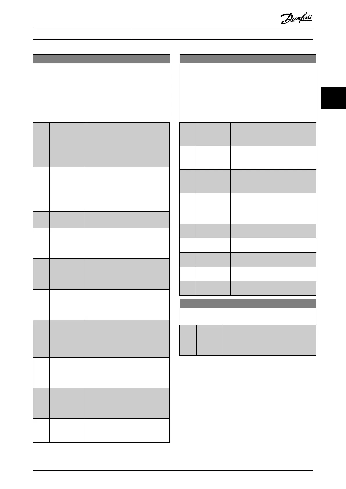
5-40 Function Relay
Array (Relay 1 [0], Relay 2 [1])
Select options to dene the function of the relays.
The selection of each mechanical relay is realized in an array
parameter. When parameter 0-03 Regional Settings is set to [0]
International, the default value is [9] Alarm. When
parameter 0-03 Regional Settings is set to [1] North America, the
default value is [160] No alarm.
Option: Function:
[82] SL digital
output C
See parameter 13-52 SL Controller Action.
The input goes high whenever the smart
logic action [40] Set dig. out. C high is
executed. The input goes low whenever
the smart logic [34] Action Set dig. out. C
low is executed.
[83] SL digital
output D
See parameter 13-52 SL Controller Action.
The input goes high whenever the smart
logic [41] Action Set dig. out. D high is
executed. The input goes low whenever
the smart logic [35] Action Set dig. out. D
low is executed.
[160] No alarm The output is high when no alarm is
present.
[161] Running
reverse
The output is high when the frequency
converter is running counterclockwise
(the logical product of the status bits
running and reverse).
[165] Local ref.
active
The output is high when local reference
is activated by the [Hand On] key on the
LCP or by hand-on command of digital
input.
[166] Remote ref.
active
The output is high when remote
reference is activated by the [Auto On]
key on the LCP or by auto-on command
of digital input.
[167] Start
command
activ
The output is high when there is an
active start command (that is, via digital
input bus connection or [Hand On] or
[Auto On], and no stop command is
active.
[168] Drive in hand
mode
The output is high when the frequency
converter is in hand On mode (as
indicated by the LED light above [Hand
On]).
[169] Drive in auto
mode
The output is high when the frequency
converter is in auto On mode (as
indicated by the LED light above [Auto
On]).
[190] No-Flow A no-ow condition has been detected.
See parameter group 22-2* No-Flow
Detection.
5-40 Function Relay
Array (Relay 1 [0], Relay 2 [1])
Select options to dene the function of the relays.
The selection of each mechanical relay is realized in an array
parameter. When parameter 0-03 Regional Settings is set to [0]
International, the default value is [9] Alarm. When
parameter 0-03 Regional Settings is set to [1] North America, the
default value is [160] No alarm.
Option: Function:
[193] Sleep Mode The frequency converter/system has
entered sleep mode. See parameter
group 22-4* Sleep Mode.
[194] Broken Belt
Function
A broken-belt condition has been
detected. Enable the function in
parameter 22-60 Broken Belt Function.
[196] Fire Mode The frequency converter is operating in
re mode. See parameter group 24-0*
Fire Mode.
[198] Drive Bypass To be used as a signal for activating an
external electromechanical bypass,
switching the motor directly on line.
See parameter group 24-1* Drive Bypass.
[211] Cascade Pump
1
[212] Cascade Pump
2
[213] Cascade Pump
3
[214] Cascade Pump
4
[215] Cascade Pump
5
5-41 On Delay, Relay
Array [2]
Range: Function:
0.01 s* [0.01 -
600 s]
Enter the delay of the relay cut-in time.
Select 1 of 2 internal mechanical relays in
an array function. See
parameter 5-40 Function Relay for details.
Parameters Programming Guide
MG18B502 Danfoss A/S © 04/2018 All rights reserved. 53
3 3

 Loading...


