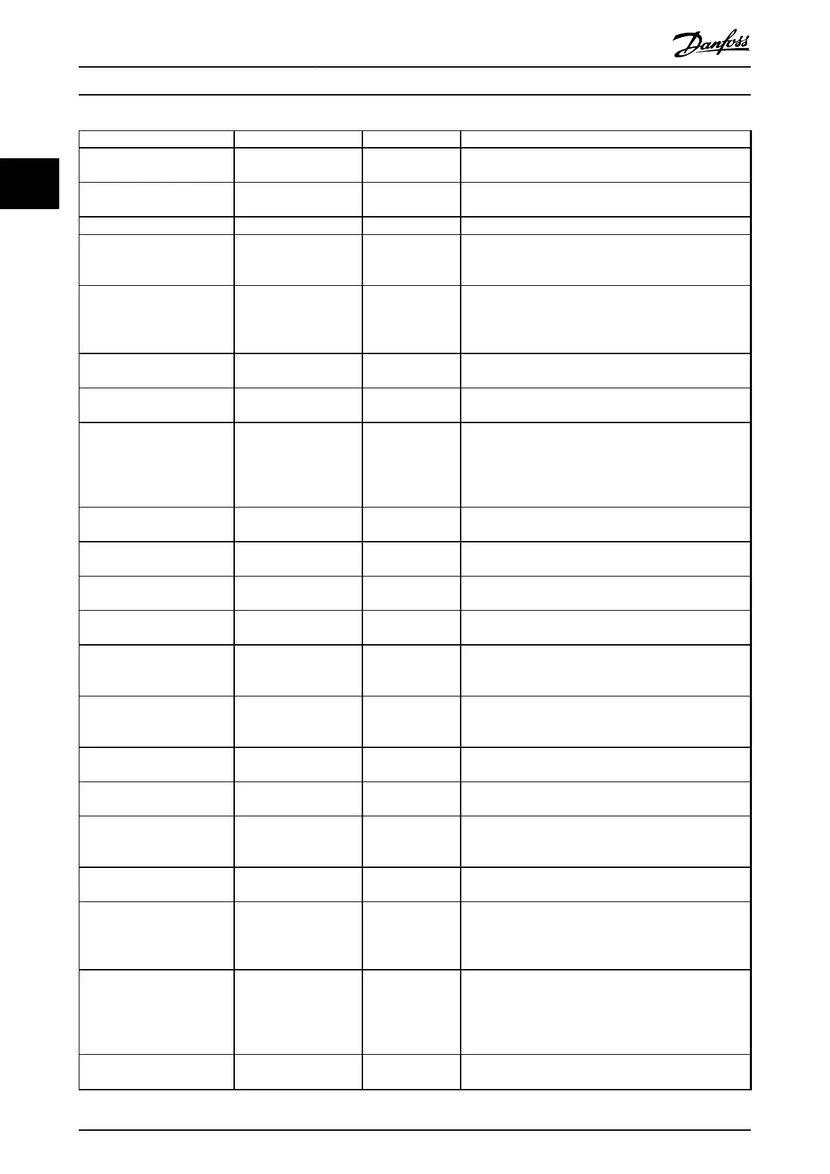
Parameter Range Default Usage
Parameter 3-02 Minimum
Reference
-4999.000–4999.000 0 The minimum reference is the lowest value obtainable by
summing all references.
Parameter 3-03 Maximum
Reference
-4999.000–4999.000 50 The maximum reference is the highest value obtainable by
summing all references.
Parameter 3-10 Preset Reference -100–100% 0 Enter the setpoint.
Parameter 3-41 Ramp 1 Ramp
Up Time
0.05–3600.0 s Size related Ramp-up time from 0 to rated parameter 1-23 Motor
Frequency for asynchronous motors. Ramp-up time from 0
to parameter 1-25 Motor Nominal Speed for PM motors.
Parameter 3-42 Ramp 1 Ramp
Down Time
0.05–3600.0 s Size related Ramp-down time from rated parameter 1-23 Motor
Frequency to 0 for asynchronous motors. Ramp-down time
from parameter 1-25 Motor Nominal Speed to 0 for PM
motors.
Parameter 4-12 Motor Speed
Low Limit [Hz]
0.0–400.0 Hz 0.0 Hz Enter the minimum limit for low speed.
Parameter 4-14 Motor Speed
High Limit [Hz]
0.0–400.0 Hz 100 Hz Enter the maximum limit for high speed.
Parameter 4-19 Max Output
Frequency
0.0–400.0 Hz 100 Hz Enter the maximum output frequency value. If
parameter 4-19 Max Output Frequency is set lower than
parameter 4-14 Motor Speed High Limit [Hz],
parameter 4-14 Motor Speed High Limit [Hz] is set equal to
parameter 4-19 Max Output Frequency automatically.
Parameter 6-20 Terminal 54 Low
Voltage
0.00–10.00 V 0.07 V Enter the voltage that corresponds to the low reference
value.
Parameter 6-21 Terminal 54
High Voltage
0.00–10.00 V 10.00 V Enter the voltage that corresponds to the high reference
value.
Parameter 6-22 Terminal 54 Low
Current
0.00–20.00 mA 4.00 mA Enter the current that corresponds to the low reference
value.
Parameter 6-23 Terminal 54
High Current
0.00–20.00 mA 20.00 mA Enter the current that corresponds to the high reference
value.
Parameter 6-24 Terminal 54 Low
Ref./Feedb. Value
-4999–4999 0 Enter the feedback value that corresponds to the voltage
or current set in parameter 6-20 Terminal 54 Low Voltage/
parameter 6-22 Terminal 54 Low Current.
Parameter 6-25 Terminal 54
High Ref./Feedb. Value
-4999–4999 50 Enter the feedback value that corresponds to the voltage
or current set in parameter 6-21 Terminal 54 High Voltage/
parameter 6-23 Terminal 54 High Current.
Parameter 6-26 Terminal 54
Filter Time Constant
0.00–10.00 s 0.01 Enter the lter time constant.
Parameter 6-29 Terminal 54
mode
[0] Current
[1] Voltage
[1] Voltage Select if terminal 54 is used for current or voltage input.
Parameter 20-81 PI Normal/
Inverse Control
[0] Normal
[1] Inverse
[0] Normal Select [0] Normal to set the process control to increase the
output speed when the process error is positive. Select [1]
Inverse to reduce the output speed.
Parameter 20-83 PI Start Speed
[Hz]
0–200 Hz 0 Hz Enter the motor speed to be attained as a start signal for
commencement of PI control.
Parameter 20-93 PI Proportional
Gain
0.00–10.00 0.01 Enter the process controller proportional gain. Quick
control is obtained at high amplication. However, if
amplication is too high, the process may become
unstable.
Parameter 20-94 PI Integral
Time
0.1–999.0 s 999.0 s Enter the process controller integral time. Obtain quick
control through a short integral time, though if the
integral time is too short, the process becomes unstable.
An excessively long integral time disables the integral
action.
Parameter 30-22 Locked Rotor
Protection
[0] O
[1] On
[0] O
–
Programming
VLT
®
HVAC Basic Drive FC 101
20 Danfoss A/S © 04/2018 All rights reserved. MG18B502
22

 Loading...


