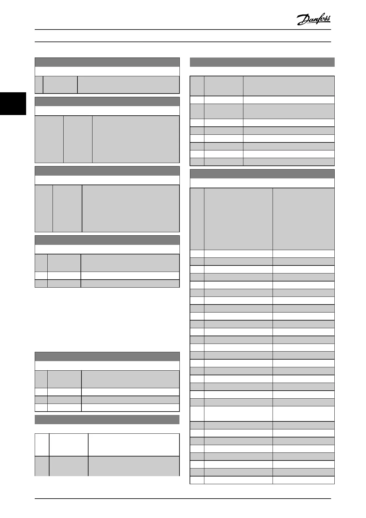
6-24 Terminal 54 Low Ref./Feedb. Value
Range: Function:
parameter 6-21 Terminal 54 High Voltage/
parameter 6-22 Terminal 54 Low Current.
6-25 Terminal 54 High Ref./Feedb. Value
Range: Function:
Size
related*
[-4999 -
4999 ]
Enter the reference or feedback value
that corresponds to the voltage or
current set in parameter 6-21 Terminal
54 High Voltage/
parameter 6-23 Terminal 54 High
Current.
6-26 Terminal 54 Filter Time Constant
Range: Function:
0.01 s* [0.01 - 10
s]
Enter the time constant, which is a rst-
order digital low-pass lter time constant
for suppressing electrical noise in terminal
54. A high time constant value improves
dampening, but also increases the time
delay through the lter.
6-29 Terminal 54 mode
Option: Function:
Select if terminal 54 is used for current
input or voltage input.
[0] Current mode
[1] * Voltage mode
3.7.4 6-7* Analog/Digital Output 45
Parameters for conguring the scaling and limits for
analog/digital output terminal 45. Analog outputs are
current outputs: 0/4–20 mA. Resolution on analog output
is 12 bit. Analog output terminals can also be set up as
digital output.
6-70 Terminal 45 Mode
Option: Function:
Set terminal 45 to act as analog output or
as digital output.
[0] * 0-20 mA
[1] 4-20 mA
[2] Digital Output
6-71 Terminal 45 Analog Output
Option: Function:
Select the function of terminal 45 as an
analog current output. See also
parameter 6-70 Terminal 45 Mode.
[254] DC-link voltage
•
T2/S2, 200–400 V
•
T4, 400–800 V
6-71 Terminal 45 Analog Output
Option: Function:
•
T5, 400–1000 V
•
T6, 500–1000 V
[0] * No operation
[100] Output
frequency
0–100 Hz
[101] Reference Min
Ref.
–Max
Ref.
[102] Feedback Min
FB
–Max
FB
[103] Motor Current 0–I
max
[106] Power 0–P
nom
[139] Bus Control 0–100%
[254] DC Link Voltage 0–65535 V
6-72 Terminal 45 Digital Output
Option: Function:
Select the function of
terminal 45 as a digital
current output. See also
parameter 6-70 Terminal 45
Mode. See
parameter 5-40 Function
Relay for description of the
options.
[0] * No operation
[1] Control Ready
[2] Drive ready
[3] Drive ready/remote control
[4] Standby / no warning
[5] Drive running
[6] Running / no warning
[7] Run in range/no warning
[8] Run on ref/no warning
[9] Alarm
[10] Alarm or warning
[12] Out of current range
[13] Below current, low
[14] Above current, high
[16] Below speed, low
[17] Above speed, high
[19] Below feedback, low
[20] Above feedback, high
[21] Thermal warning
[22] Ready, no thermal warning
[23] Remote, ready, no thermal
warning
[24] Ready, Voltage OK
[25] Reverse
[26] Bus OK
[35] External Interlock
[36] Control word bit 11
[37] Control word bit 12
[41] Below reference, low
[42] Above ref, high
Parameters
VLT
®
HVAC Basic Drive FC 101
58 Danfoss A/S © 04/2018 All rights reserved. MG18B502
33

 Loading...


