6-72 Terminal 45 Digital Output
Option: Function:
[45] Bus Control
[60] Comparator 0
[61] Comparator 1
[62] Comparator 2
[63] Comparator 3
[64] Comparator 4
[65] Comparator 5
[70] Logic rule 0
[71] Logic rule 1
[72] Logic rule 2
[73] Logic rule 3
[74] Logic rule 4
[75] Logic rule 5
[80] SL digital output A
[81] SL digital output B
[82] SL digital output C
[83] SL digital output D
[160] No alarm
[161] Running reverse
[165] Local ref. active
[166] Remote ref. active
[167] Start command activ
[168] Drive in hand mode
[169] Drive in auto mode
[190] No-Flow
[193] Sleep Mode
[194] Broken Belt Function
[196] Fire Mode
[198] Drive Bypass
6-73 Terminal 45 Output Min Scale
Range: Function:
0 %* [0 -
200 %]
Scale for the minimum output (0 mA or 4 mA)
of the analog signal at terminal 45. Set the
value to be the percentage of the full range of
the variable selected in parameter 6-71 Terminal
45 Analog Output.
6-74 Terminal 45 Output Max Scale
Range: Function:
100
%*
[0 -
200 %]
Scale for the maximum output (20 mA) of the
analog signal at terminal 45. Set the value to be
the percentage of the full range of the variable
selected in parameter 6-71 Terminal 45 Analog
Output.
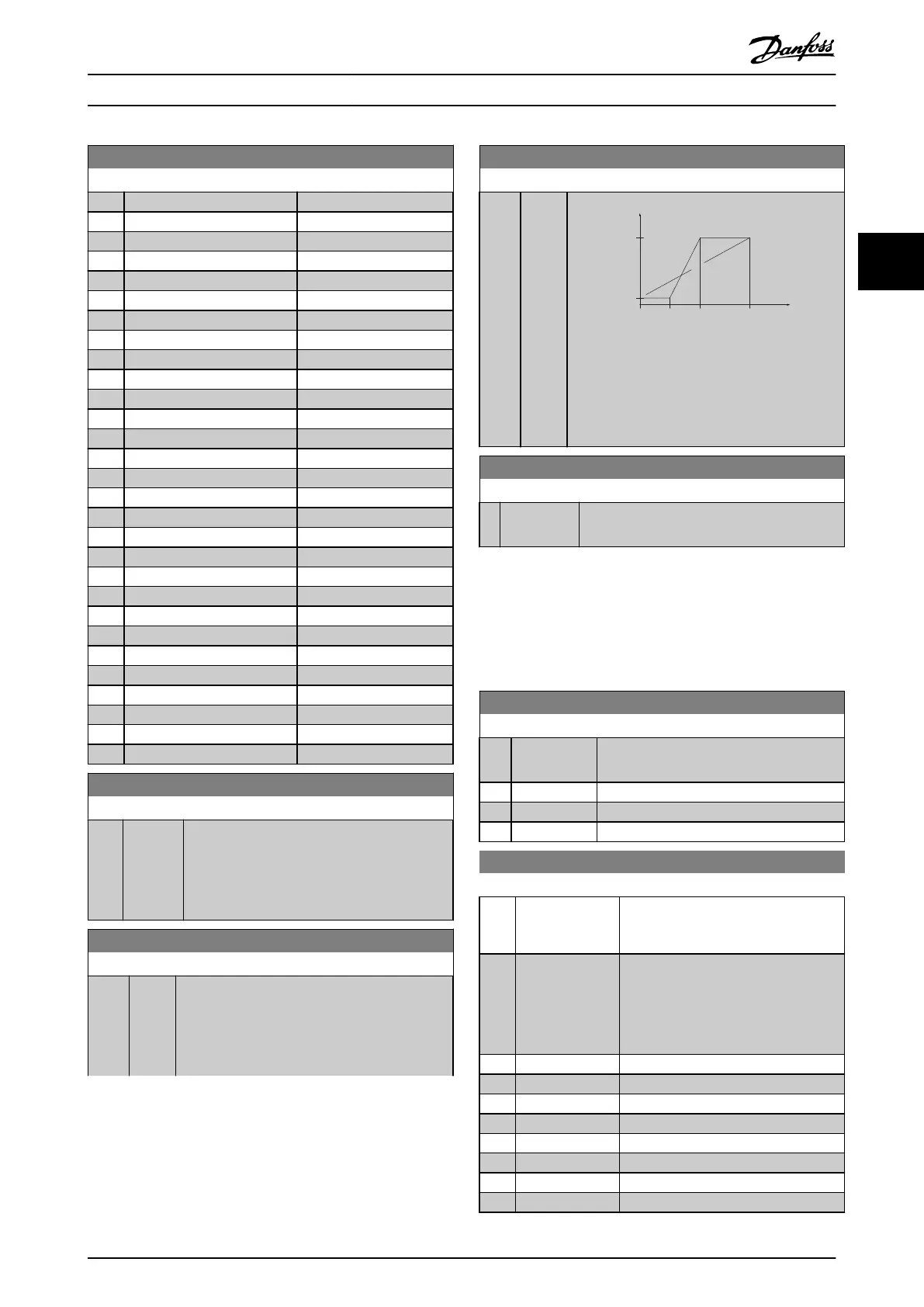
6-74 Terminal 45 Output Max Scale
Range: Function:
(mA)
0%
20
0/4
100%
Current
Analogue
output
Min Scale
par. 6-73
Variable
for
output
example:
Power
Analogue
Output
Max Scale
par. 6-74
Illustration 3.11 Output Maximum Scale
6-76 Terminal 45 Output Bus Control
Range: Function:
0* [0 - 16384 ] Holds the level of analog output if controlled
by bus.
3.7.5 6-9* Analog/Digital Output 42
Parameters for conguring the limits for analog/digital
output terminal 42. Analog outputs are current outputs:
0/4–20 mA. Resolution on analog outputs is 12 bit. Analog
output terminals can also be set up as digital output.
6-90 Terminal 42 Mode
Option: Function:
Set terminal 42 to act as analog output or
as digital output.
[0] * 0-20 mA
[1] 4-20 mA
[2] Digital Output
6-91 Terminal 42 Analog Output
Option: Function:
Select the function of terminal 42 as an
analog current output. See also
parameter 6–90 Terminal 42 Mode.
[254] DC-link voltage
•
T2/S2, 200–400 V
•
T4, 400–800 V
•
T5, 400–1000 V
•
T6, 500–1000 V
[0] * No operation
[100] Output frequency 0–100 Hz
[101] Reference Min
Ref.
– Max
Ref.
[102] Feedback Min
FB
– Max
FB
[103] Motor Current 0–I
max
[106] Power 0–P
nom
[139] Bus Control 0–100%
[184] Mirror AI53 mA 0–20
Parameters Programming Guide
MG18B502 Danfoss A/S © 04/2018 All rights reserved. 59
3 3

 Loading...


