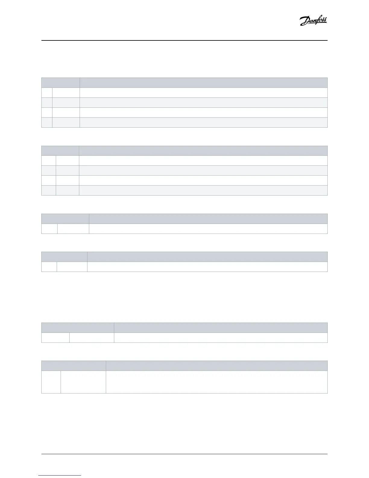
6.4.1.3 Parameter Group 30-** Pump Input Configuration
Table 17: 30-1 - Pressure Sensor Type
Option Function
Selects which type of sensor is associated with the pressure sensor input on the smart card.
* None
Switch
Analog
Table 18: 30-2 - Pressure Units
Option Function
Selects which units the sensor uses to report the measured pressure.
Bar
* kPa
Psi
Table 19: 30-3 - Pressure at 4 mA
Range Function
*0 0–5000 Calibrates the soft starter to the 4 mA (0%) level of the pressure sensor input.
Table 20: 30-4 - Pressure at 20 mA
Range Function
*0 0–5000 Calibrates the soft starter to the 20 mA (100%) level of the pressure sensor input.
6.4.1.4 Parameter Group 32-** Pressure Protection
Pressure protection uses terminals B23, B24 or C33, C34, C44 on the smart card.
Table 21: 32-1 - High Pressure Trip Level
Range Function
*10 0–5000 Sets the trip point for high-pressure protection.
Table 22: 32-2 - High Pressure Start Delay
Range Function
* 0.5 s 00:00:100–
30:00:000
mm:ss:ms
Sets a delay before a high-pressure protection trip can occur. The delay is counted from the time a
start signal is received. The pressure is ignored until the start delay has elapsed.
Configuration
Installation Guide | Pumping Smart Card
AN279052730268en-000102 / 175R1183
18 | Danfoss A/S © 2018.10

 Loading...


