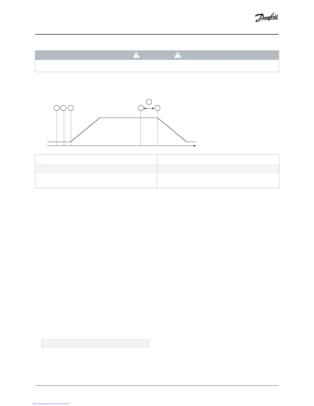
A Off (ready)
C Start signal
E Protection response (parameter 36-3 Depth Sensor and
parameter 36-9 Well Depth)
B Depth protection active
D Protection event (parameter 34-1 Depth Trip Level)
1 Depth protection response delay (parameter 34-4 Depth
Response Delay)
Illustration 8: Operation - Depth Protection
6.6.1.1 Using an Analog 4–20 mA Sensor
Context:
An analog 4–20 mA sensor provides protection and monitoring.
Procedure
1. Connect the sensor to B13, B14.
2. Set parameter 30-12 Depth Sensor Type to Analog.
3. Set parameters 30-13 to 30-15 according to the sensor specifications.
4. Set parameters 34-1 to 34-4, parameter 36-3 Depth Sensor, and parameter 36-9 Well Depth as required.
6.6.1.2 Using a Switch Sensor
Context:
A switch sensor provides protection only.
Procedure
1. Connect the sensor to C13, C14.
2. Set parameter 30-12 Depth Sensor Type to Switch.
3. Set parameters 34-3 to 34-4, parameter 36-3 Depth Sensor, and parameter 36-9 Well Depth as required.
Parameters 34-1 to 34-2 are not used with a switch sensor.
Configuration
Installation Guide | Pumping Smart Card
AN279052730268en-000102 / 175R1183 | 25
Danfoss A/S © 2018.10

 Loading...


