•
•
-
-
-
-
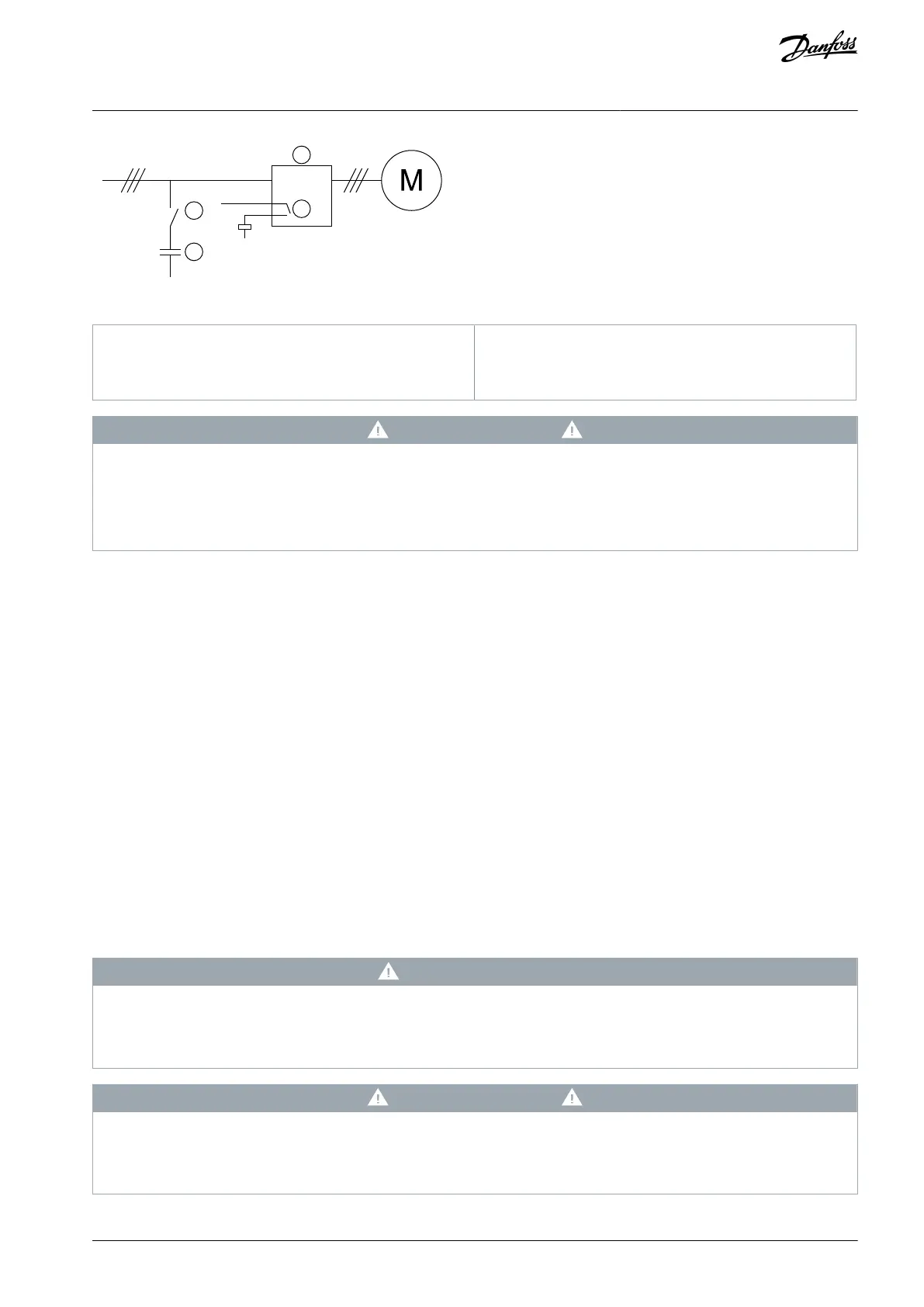
Illustration 6: Connection Diagram
Programmable output (set=Run)
Power factor correction contactor
C A U T I O N
EQUIPMENT DAMAGE
Connecting power factor correction capacitors to the output side damages the soft starter.
Always connect power factor correction capacitors to the input side of the soft starter.
Do not use the soft starter relay output to switch in power factor correction directly.
3.13 Short-circuit Protection Devices
When designing motor circuit protection schemes, the IEC 60947-4-1 standard on soft starters and contactors defines 2 types of
coordination regarding soft starters:
Type 1 coordination.
Type 2 coordination.
3.13.1 Type 1 Coordination
Type 1 coordination requires that, if there is a short circuit on the output side of a soft starter, the fault must be cleared without risk
of injury to personnel and damage to installations. There is no requirement that the soft starter must remain operational after the
fault. For the soft starter to become operational again, repair and replacement of parts are required.
HRC fuses (such as Ferraz/Mersen AJT fuses) can be used for Type 1 coordination according to the IEC 60947-4-2 standard.
3.13.2 Type 2 Coordination
Type 2 coordination requires that, if there is a short circuit on the output side of a soft starter, the fault must be cleared without risk
of injury to personnel or damage to the soft starter.
Type 2 coordination has the advantage that, after the fault is cleared, authorized personnel can replace the blown fuses and check
contactors for any welding. The soft starter is then operational again.
Semiconductor fuses for Type 2 circuit protection are extra to HRC fuses or MCCBs that form part of the motor branch circuit protec-
tion.
C A U T I O N
DC BRAKE
A high brake torque setting can result in peak currents up to motor DOL being drawn while the motor is stopping.
Ensure that protection fuses installed in the motor branch circuit are selected appropriately.
C A U T I O N
NO BRANCH CIRCUIT PROTECTION
Integral solid-state short-circuit protection does not provide branch circuit protection.
Provide branch circuit protection in accordance with the National Electrical Code and any additional local codes.
AQ262141844215en-000401 / 175R1174 | 23Danfoss A/S © 2020.12
System Design
VLT® Soft Starter MCD 600
Operating Guide