•
•
•
•
1/L1
3/L2
5/L3
2/T1
4/T2
6/T3
1/L1 3/L2
5/L3
T1B T2B T3B
1/L1 3/L2
5/L3
2/T1
4/T2
6/T3
2/T1
4/T2
6/T3
MCD6-0020B-
MCD6-0129B
MCD6-0144B-MCD6-0579B
&
MCD6-0160C-MCD6-0448C
MCD6-0654B-MCD6-1250B
MCD6-0590C-MCD6-1220C
1/L1
3/L2
5/L3
2/T1
4/T2
6/T3
e77ha822.10
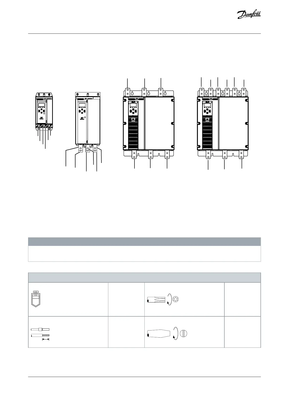
Illustration 13: Input and Output Terminals for Power Terminations
Models MCD6-0020B~MCD6-0129B use cage clamps. Use copper stranded or solid conductors rated for 75 °C (167 °F) or higher.
Models MCD6-0144B~MCD6-1250B and MCD6-0160C~MCD6-1134C use busbars. Use copper or aluminum conductors, stran-
ded or solid, rated for 60/75 °C (140/167 °F).
Models MCD6-0654B~MCD6-1250B/MCD6-0160C~MCD6-1134C use busbars. Input terminals are at the top of the unit and out-
put terminals are at the bottom.
Models MCD6-0590C~MCD6-1134C have dedicated bypass terminals, if the soft starter will be installed with an external bypass
contactor. The bypass busbars are at the top of the unit and are labeled T1B, T2B, T3B.
N O T I C E
When connecting power terminations, clean the surface contact area thoroughly (using an emery or stainless steel brush) and
use an appropriate jointing compound to prevent corrosion.
Table 21: Power Terminations, MCD6-0020B~MCD6-0129B
Cable size: 6–
70 mm
2
(AWG 10–2/0)
Torque: 4 Nm
(2.9 ft-lb)
AQ262141844215en-000401 / 175R1174 | 37Danfoss A/S © 2020.12
Installation
VLT® Soft Starter MCD 600
Operating Guide