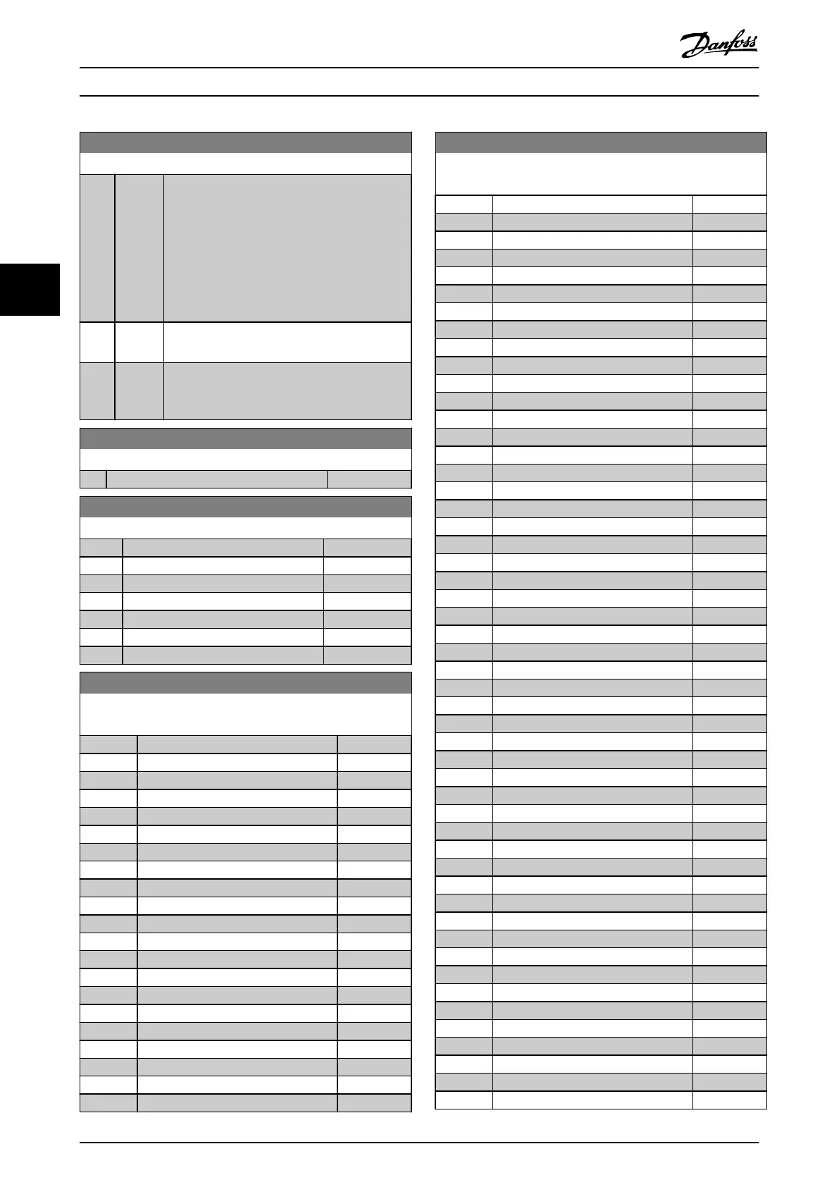
0-12 Link Setups
Option: Function:
The link ensures synchronising of the Not
changeable during operation parameter values
enabling shift from 1 set-up to another during
operation.
If the set-ups are not linked, a change between
them is not possible while the motor runs. Thus
the set-up change does not occur until the
motor is coasted.
[0] Not
linked
Leaves parameters unchanged in both set-ups
and cannot be changed while the motor runs.
[20] * Linked Copies Not changeable during operation
parameters from 1 set-up to the other, so they
are identical in both set-ups.
0-14 Readout: Edit Set-ups / Channel
Range: Function:
0* [-2147483647 - 2147483647 ]
0-16 Application Selection
Option: Function:
[0] * None
[1] Simple Process Close Loop
[2] Local/Remote
[3] Speed Open Loop
[4] Simple Speed Close Loop
[5] Multi Speed
[6] OGD Function
0-20 Display Line 1.1 Small
Select a variable to display in line 1, left position.
Option: Function:
[0]
[37] Display Text 1
[38] Display Text 2
[39] Display Text 3
[748] PCD Feed Forward
[953] Probus Warning Word
[1005] Readout Transmit Error Counter
[1006] Readout Receive Error Counter
[1501] Running Hours
[1502] kWh Counter
[1600] Control Word
[1601] Reference [Unit]
[1602] * Reference [%]
[1603] Status Word
[1605] Main Actual Value [%]
[1609] Custom Readout
[1610] Power [kW]
[1611] Power [hp]
[1612] Motor Voltage
[1613] Frequency
[1614] Motor current
0-20 Display Line 1.1 Small
Select a variable to display in line 1, left position.
Option: Function:
[1615] Frequency [%]
[1616] Torque [Nm]
[1618] Motor Thermal
[1620] Motor Angle
[1622] Torque [%]
[1630] DC Link Voltage
[1633] Brake Energy /2 min
[1634] Heatsink Temp.
[1635] Inverter Thermal
[1636] Inv. Nom. Current
[1637] Inv. Max. Current
[1638] SL Controller State
[1639] Control Card Temp.
[1650] External Reference
[1652] Feedback[Unit]
[1653] Digi Pot Reference
[1657] Feedback [RPM]
[1660] Digital Input
[1661] Terminal 53 Setting
[1662] Analog Input 53
[1663] Terminal 54 Setting
[1664] Analog Input AI54
[1665] Analog Output 42 [mA]
[1666] Digital Output
[1667] Pulse Input 29[Hz]
[1668] Pulse Input 33 [Hz]
[1669] Pulse Output 27 [Hz]
[1671] Relay Output
[1672] Counter A
[1673] Counter B
[1674] Prec. Stop Counter
[1680] Fieldbus CTW 1
[1682] Fieldbus REF 1
[1684] Comm. Option STW
[1685] FC Port CTW 1
[1686] FC Port REF 1
[1690] Alarm Word
[1691] Alarm Word 2
[1692] Warning Word
[1693] Warning Word 2
[1694] Ext. Status Word
[1695] Ext. Status Word 2
[1697] Alarm Word 3
[1890] Process PID Error
[1891] Process PID Output
[1892] Process PID Clamped Output
[1893] Process PID Gain Scaled Output
[2117] Ext. 1 Reference [Unit]
[2118] Ext. 1 Feedback [Unit]
[2119] Ext. 1 Output [%]
[3401] PCD 1 Write For Application
Parameter Descriptions
VLT
®
Midi Drive FC 280
24 Danfoss A/S © 12/2015 All rights reserved. MG07C102
44

 Loading...


