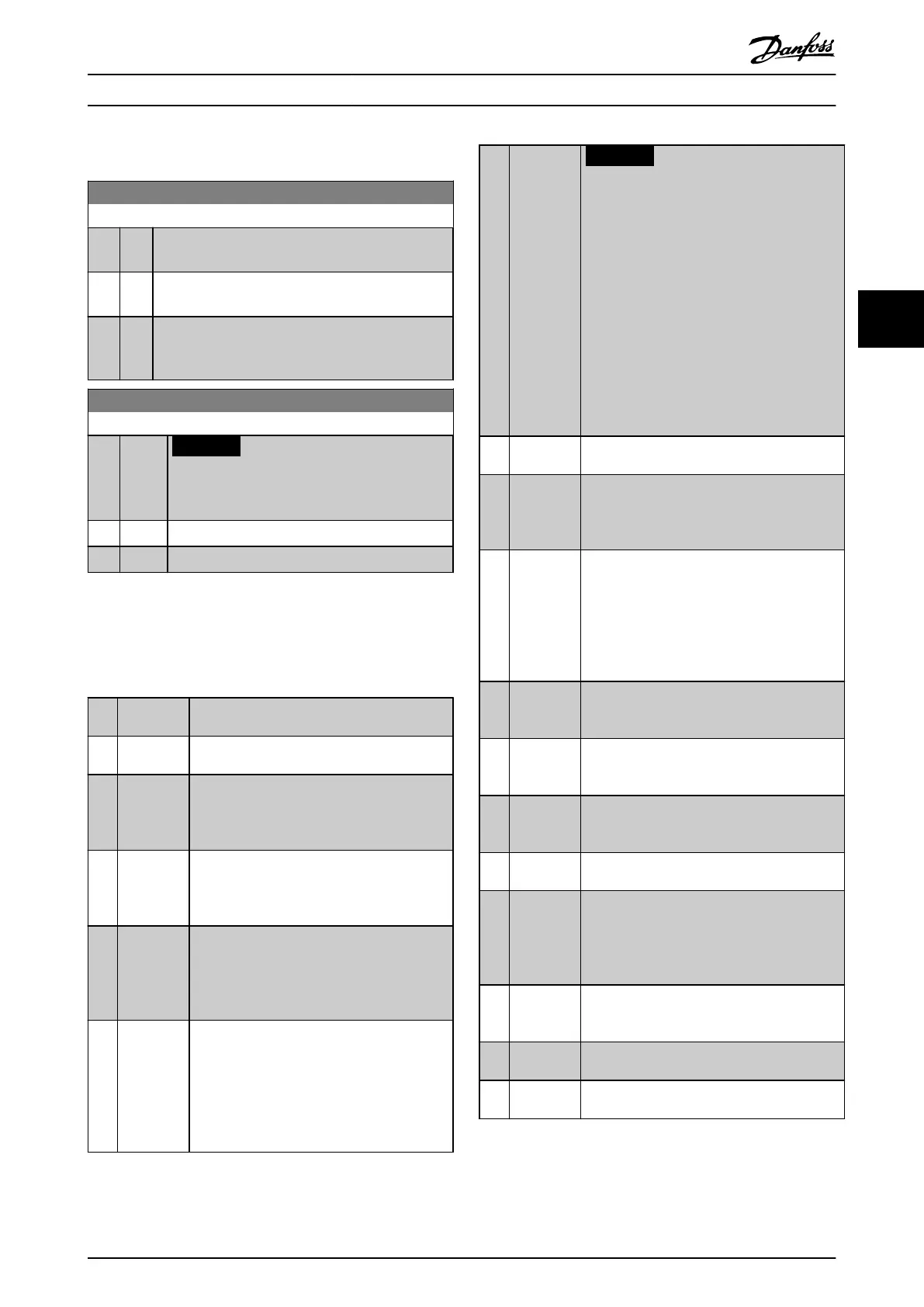
4.6 Parameters: 5-** Digital In/Out
5-00 Digital Input Mode
Option: Function:
Set NPN or PNP mode for digital inputs 18, 19, and
27. Digital input mode.
[0] * PNP Action on positive directional pulses (0). PNP systems
are pulled down to ground (GND).
[1] NPN Action on negative directional pulses (1). NPN
systems are pulled up to +24 V, internally in the
frequency converter.
5-01 Terminal 27 Mode
Option: Function:
NOTICE
This parameter cannot be adjusted while
the motor is running.
[0] * Input Denes terminal 27 as a digital input.
[1] Output Denes terminal 27 as a digital output.
4.6.1 5-1* Digital Inputs
The digital inputs are used for selecting various functions
in the frequency converter.
5-10 to 5-15 Digital Inputs
[0] No
operation
No reaction to signals transmitted to the
terminal.
[1] Reset Resets frequency converter after a trip/alarm.
Not all alarms can be reset.
[2] Coast
inverse
(Default Digital input 27): Coasting stop,
inverted input (NC). The frequency converter
leaves the motor in free mode. Logic
0⇒coasting stop.
[3] Coast and
reset
inverse
Reset and coasting stop inverted input (NC).
Leaves motor in free mode and resets
frequency converter. Logic 0⇒coasting stop
and reset.
[4] Quick stop
inverse
Inverted input (NC). Generates a stop in
accordance with the quick stop ramp time set
in parameter 3-81 Quick Stop Ramp Time. When
the motor stops, the shaft is in free mode.
Logic 0⇒Quick-stop.
[5] DC-brake
inverse
Inverted input for DC braking (NC). Stops the
motor by energizing it with a DC current for a
certain time period. See parameter 2-01 DC
Brake Current to parameter 2-04 DC Brake Cut In
Speed [Hz]. The function is only active when
the value in parameter 2-02 DC Braking Time is
dierent from 0. Logic 0⇒DC braking.
[6] Stop
inverse
NOTICE
When the frequency converter is at the
torque limit and has received a stop
command, it may not stop by itself. To
ensure that the frequency converter
stops, congure a digital output to [27]
Torque limit and stop and connect this
digital output to a digital input that is
congured as coast.
Stop inverted function. Generates a stop
function when the selected terminal goes from
logic 1 to logic 0. The stop is performed
according to the selected ramp time
(parameter 3-42 Ramp 1 Ramp Down Time,
parameter 3-52 Ramp 2 Ramp Down Time).
[8] Start Default digital input 18. Select start for a start/
stop command. Logic 1=start, logic 0=stop.
[9] Latched
start
The motor starts when a pulse is applied for
minimum 2 ms. The motor stops when [6] Stop
inverse is activated or a reset command (via DI)
is given.
[10] Reversing Default digital input 19. Change the direction
of motor shaft rotation. Select logic 1 to
reverse. The reversing signal only changes the
direction of rotation. It does not activate the
start function. Select both directions in
parameter 4-10 Motor Speed Direction. The
function is not active in process closed loop.
[11] Start
reversing
Used for start/stop and for reversing on the
same wire. Signals on start are not allowed at
the same time.
[12] Enable
start
forward
Disengages the counterclockwise movement
and allows for the clockwise direction.
[13] Enable
start
reverse
Disengages the clockwise movement and
allows for the counterclockwise direction.
[14] Jog Default digital input 29. Use to activate jog
speed. See parameter 3-11 Jog Speed [Hz].
[15] Preset
reference
on
Shifts between external reference and preset
reference. It is assumed that [1] External/preset
has been selected in parameter 3-04 Reference
Function. Logic 0=external reference active;
logic 1=1 of the 8 preset references is active.
[16] Preset ref
bit 0
Preset reference bits 0, 1, and 2 enable the
selection of 1 of the 8 preset references
according to Table 4.1.
[17] Preset ref
bit 1
Same as [16] Preset ref bit 0.
[18] Preset ref
bit 2
Same as [16] Preset ref bit 0.
Parameter Descriptions Programming Guide
MG07C102 Danfoss A/S © 12/2015 All rights reserved. 51
4 4

 Loading...


