5-40 Function Relay
Option: Function:
[75] Logic rule 5 See parameter group 13-4* Logic Rules.
If logic rule 5 in SLC is TRUE, the
output goes high. Otherwise, it goes
low.
[80] SL digital output
A
See parameter 13-52 SL Controller
Action. Output A is low on [32] Smart
Logic Action. Output A is high on [38]
Smart Logic Action.
[81] SL digital output
B
See parameter 13-52 SL Controller
Action. Output B is low on [32] Smart
Logic Action. Output B is high on [38]
Smart Logic Action.
[82] SL digital output
C
See parameter 13-52 SL Controller
Action. Output C is low on [32] Smart
Logic Action. Output C is high on [38]
Smart Logic Action.
[83] SL digital output
D
See parameter 13-52 SL Controller
Action. Output D is low on [32] Smart
Logic Action. Output D is high on [38]
Smart Logic Action.
[160] No alarm The output is high when no alarm is
present.
[161] Running reverse The output is high when the frequency
converter is running counterclockwise
(the logical product of the status bits
Running AND Reverse).
[165] Local ref active
[166] Remote ref active
[167] Start command
activ
The output is high when there is an
active start command, and no stop
command is active.
[168] Drive in hand
mode
The output is high when the frequency
converter is in hand-on mode.
[169] Drive in auto
mode
The output is high when the frequency
converter is in auto-on mode.
[170] Homing
Completed
The homing operation is completed.
This option is only eective when
parameter 37-00 Application Mode is set
to [2] Position Control.
[171] Target Position
Reached
The target position is reached. This
option is only eective when
parameter 37-00 Application Mode is set
to [2] Position Control.
[172] Position Control
Fault
A fault occurred in the positioning
process. Refer to parameter 37-18 Pos.
Ctrl Fault Reason for details about the
fault. This option is only eective when
parameter 37-00 Application Mode is set
to [2] Position Control.
5-40 Function Relay
Option: Function:
[173] Position Mech
Brake
Selects mechanical control for
positioning. This option is only
eective when
parameter 37-00 Application Mode is set
to [2] Position Control.
[190] Safe Function
active
[193] Sleep Mode The frequency converter/system has
entered sleep mode. See parameter
group 22-4* Sleep Mode.
[194] Broken Belt
Function
A broken belt condition has been
detected. See parameter group 22-4*
Sleep Mode.
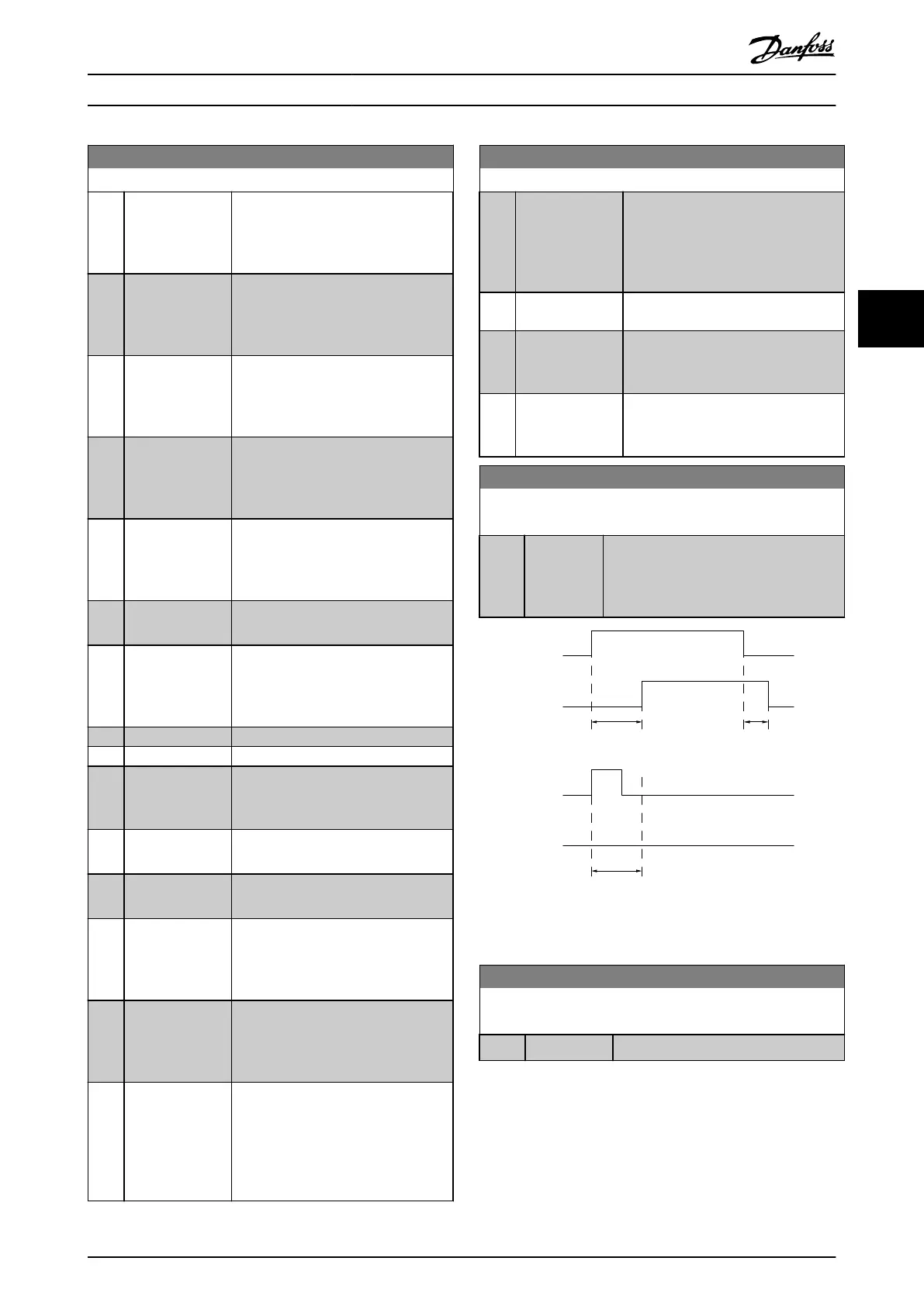
5-41 On Delay, Relay
Array [2](Relay 1 [0], Relay 2 [1])
Range: Function:
0.01 s* [0.01 - 600
s]
Enter the delay of the relay cut-in time.
The relay only cuts in if the condition in
parameter 5-40 Function Relay is uninter-
rupted during the specied time.
Selected
Event
Relay
output
Selected
Event
Relay
output
On Delay
P 5-41
On Delay
P 5-41
O Delay
P 5-42
130BA171.10
Illustration 4.10 On Delay, Relay
5-42 O Delay, Relay
Array[2]: Relay1[0], Relay2[1]
Range: Function:
0.01 s* [0.01 - 600 s] Enter the delay of the relay cut-out time.
Parameter Descriptions Programming Guide
MG07C102 Danfoss A/S © 12/2015 All rights reserved. 59
4 4

 Loading...


