• Make the shield connections with the largest possible surface area (by using a cable clamp or an EMC cable connector). This is done by using
the supplied installation devices in the adjustable frequency drive.
• Avoid terminating the shield by twisting the ends (pigtails), as this will spoil high frequency shielding effects.
• If it is necessary to break the continuity of the shield to install a motor isolator or motor relay, the continuity must be maintained with the lowest
possible HF impedance.
Cable length and cross-section
The adjustable frequency drive has been tested with a given length of cable and a given cross-section of that cable. If the cross-section is increased, the
cable capacitance - and thus the leakage current - may increase, thereby requiring that the cable length is reduced accordingly.
Switching frequency
When adjustable frequency drives are used together with sine wave filters to reduce the acoustic noise from a motor, the switching frequency must be
set according to the sine wave filter instructions in par.14-01
Switching Frequency
.
Precautions while using aluminum conductors
Aluminum conductors are not recommended for cable cross-sections less than 0.054 in² [35 mm²]. Terminals can accept aluminum conductors, but the
conductor surface has to be clean, oxidation must be removed, and the area must be sealed by neutral acid-free Vaseline grease before the conductor
is connected.
Furthermore, the terminal screw must be retightened after two days due to the softness of the aluminum. It is crucial to ensure that the connection
makes a gas tight joint, otherwise the aluminum surface will oxidize again.
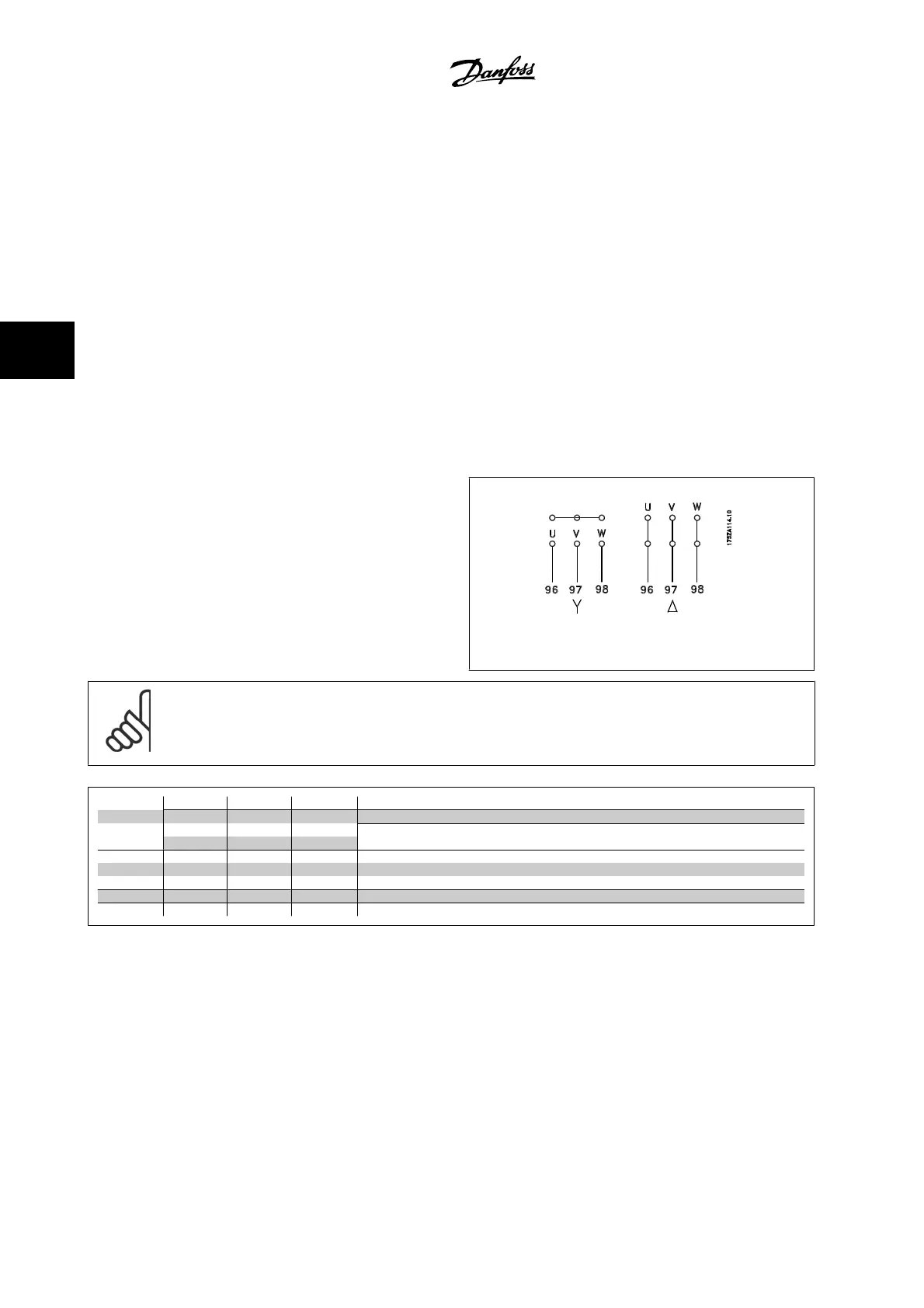
All types of three-phase asynchronous standard motors can be connected
to the adjustable frequency drive. Normally, small motors are star-con-
nected (230/400 V, D/Y). Large motors are delta-connected (400/690 V,
D/Y). Refer to the motor nameplate for correct connection mode and
voltage.
Figure 4.15: Terminals for motor connection
NOTE!
In motors without phase insulation paper or other insulation reinforcement suitable for operation with the voltage supply (such as an
adjustable frequency drive), fit a sine-wave filter on the output of the adjustable frequency drive. (Motors that comply with IEC 60034-17
do not require a sine-wave filter).
No. 96 97 98 Motor voltage 0–100% of AC line voltage.
U V W 3 cables out of motor
U1 V1 W1
6 cables out of motor, Delta-connected
W2 U2 V2
U1 V1 W1 6 cables out of motor, Star-connected
U2, V2, W2 to be interconnected separately
(optional terminal block)
No. 99 Ground connection
PE
Table 4.16: 3 and 6 cable motor connection.
4 Electrical installation VLT
®
HVAC Drive Instruction Manual
4-12
MG.11.A9.22 - VLT
®
is a registered Danfoss trademark
4