Hardware System-Level Interfaces
12 DD400 Series Restorer User Guide
• The rack screw is to keep the chassis from sliding forward and back when in a rack with slide
rails. Use a 10-32 nut to secure the rack screw to the rack.
The rack screws cannot support
the weight of the chassis in a rack. Use the rack screws only in combination with the slide
rails that are included in the shipping crate with the restorer
.
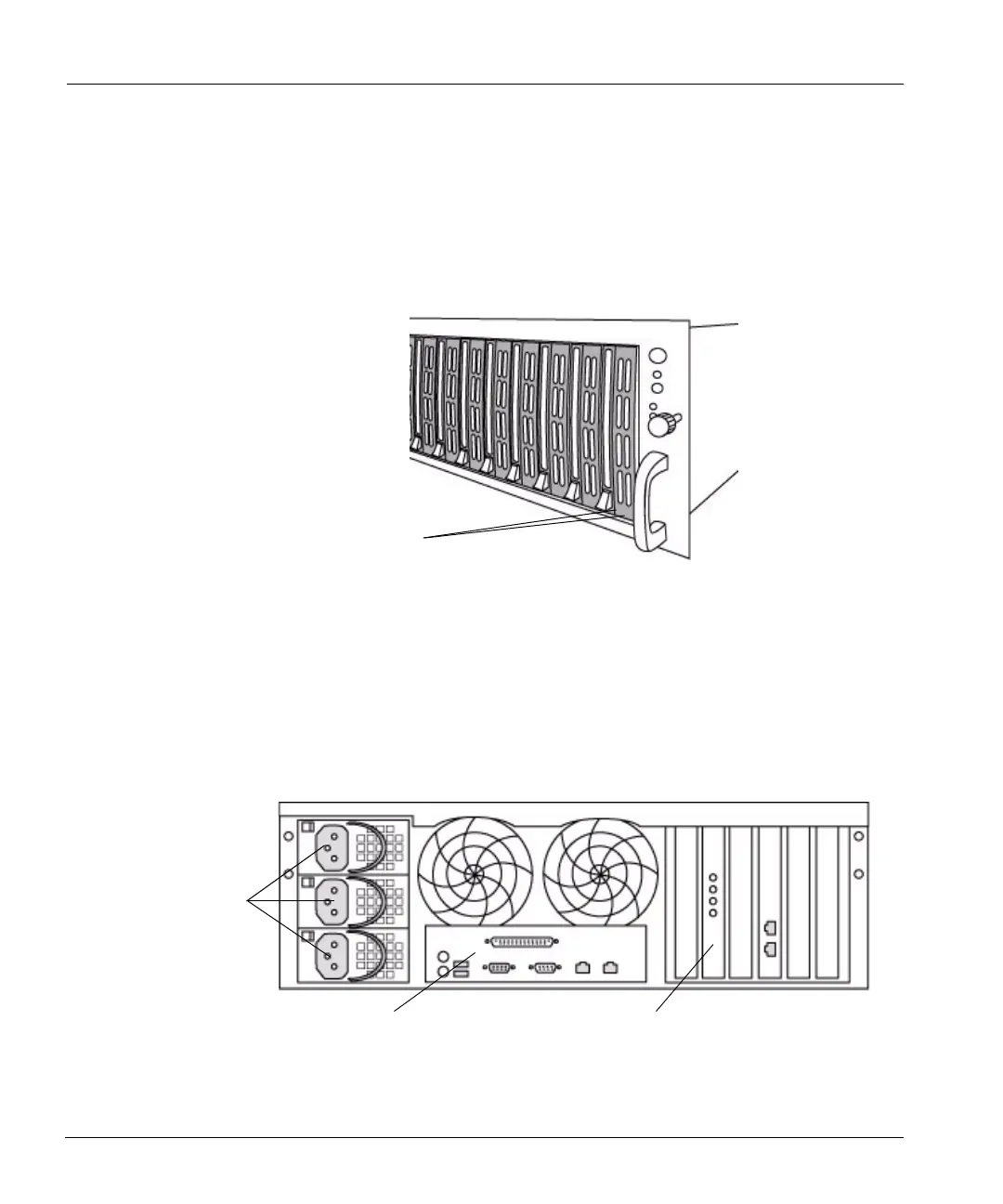
Each disk has two LEDs at the bottom of the disk carrier. See Figure 4. The right LED on each disk
flashes green whenever the system accesses the disk. The left LED glows red when the disk has
failed. Both LEDs are dark on the disk that is available as a spare.
Back Panel
The back panel has three major functional areas: the power supply units, a hardware interface
panel, and a system card interface area. See
Figure 5 on page 12.
Disk LEDs
Figure 4: Disk activity LEDs
Power
supply
units
Hardware interface panel
System card interfaces
Figure 5: Back panel
 Loading...