Chapter 1: Introduction 11
Hardware System-Level Interfaces
Hardware System-Level Interfaces
The front and back panels of a DD400 restorer have a number of LEDs and hardware interfaces.
Front Panel
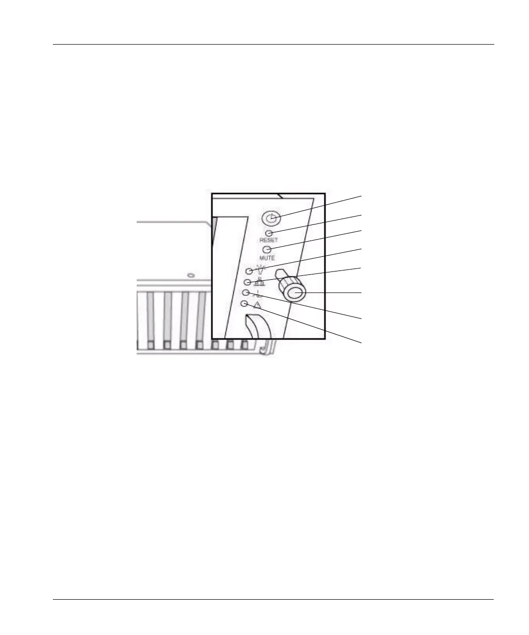
The upper right corner of the front panel has all of the front-panel interfaces (except for the disk
activity LEDs). See
Figure 3.
• At the top is the system power on/off button.
• Below the power button is a very small button labelled Reset. The button resets and reboots the
system. Do not press the button unless instructed to by Data Domain Technical Support.
• The next button down is labelled Mute and turns off the power supply alarm that buzzes when
one or more power supplies is not working.
• The top LED is the power on/off indicator that glows green when power is on.
• The second LED is the network activity indicator that flashes green with network activity
through the Ethernet port, eth0. See
“Hardware Interface” on page 13 to identify the port.
• The third LED indicates extreme high temperature for either CPU inside the chassis.
• The last LED glows amber when any one or more of the power supplies fails.
System power on/off
Reboot the system
Power supply alarm cutoff
Power on/off indicator
Power supply failure indicator
Figure 3: Front panel operations functions and indicators
Network activity indicator
Extreme temperature indicator
Rack screw
 Loading...