DM4270 – Installation Guide
204.4331.03 - October/2019
3.11.1 Pinout and Polarity
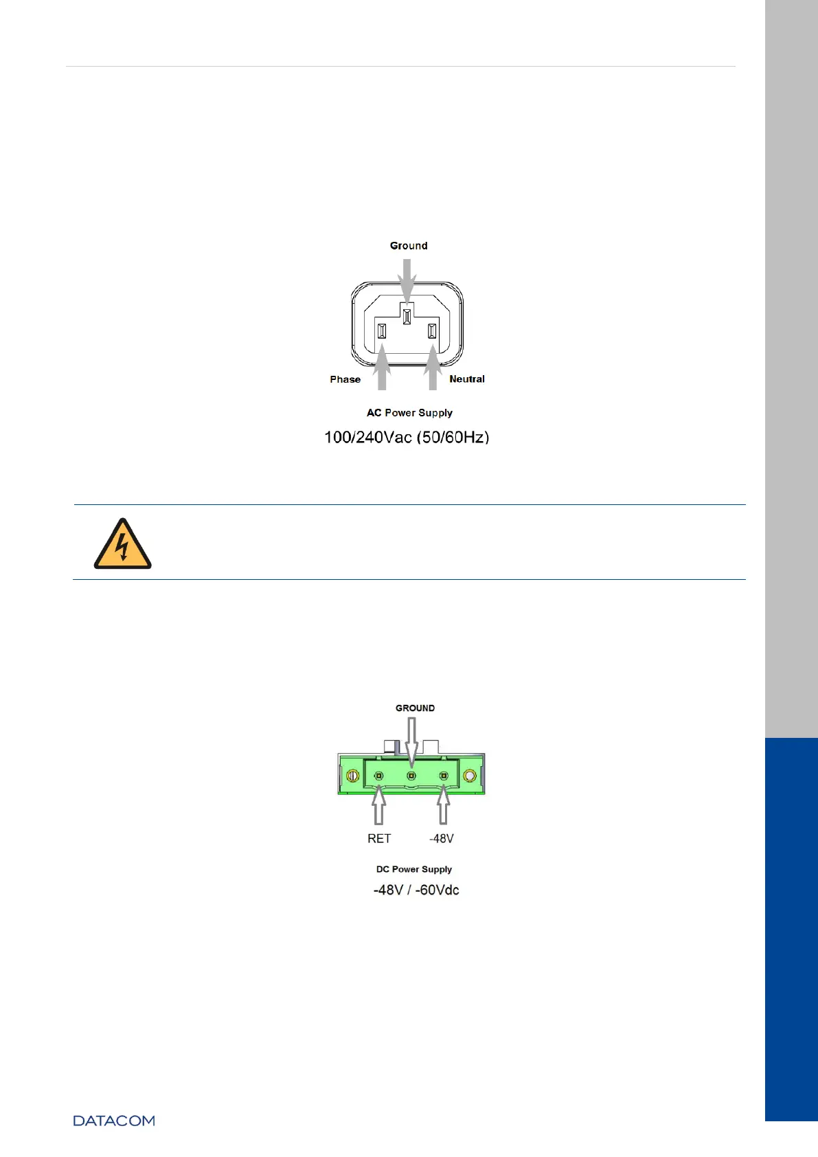
3.11.1.1 PSU 400 AC
The figure below presents the IEC 320/C14 connector pinout for the equipment’s power
supply.
Figure 15 – AC Power Connector Pinout
According to the NBR 14136 standard, the grounding pin of the product
must be connected to the grounding installations of the installation site,
since the power pins have no polarity indication.
3.11.1.2 PSU 400 DC
The figure below shows the pin settings of the TERMINAL BLOCK connector to power the
switch.
Figure 16 - DC Power Connector Pinout Settings