DKG-509 User Manual V-29 (23.08.2013)
- 31 -
The unit offers the possibility of MODBUS communication via its RS232 serial port.
The connection to the MODBUS master may be done in 3 ways:
1) RS232 connection using directly the RS232 port provided.
2) RS422/485 connection using external RS422/485 converter.
3) Modem connection using external modem.
The MODBUS mode is activated by assigning a controller address to the unit using MODBUS
Address program parameter. The possible address range is 1 to 144. Setting the address to 0 will
disable the MODBUS mode and allow communication under RAINBOW protocol.
The MODBUS properties of the unit are:
-Data transfer mode: RTU
-Serial data: 9600 bps, 8 bit data, no parity, 1 bit stop
-Supported functions:
-Function 3 (Read multiple registers)
-Function 6 (Write single register)
Detailed description about the MODBUS protocol is found in the document “Modicon Modbus
Protocol Reference Guide”. The web address is: www.modbus.org/docs/PI_MBUS_300.pdf
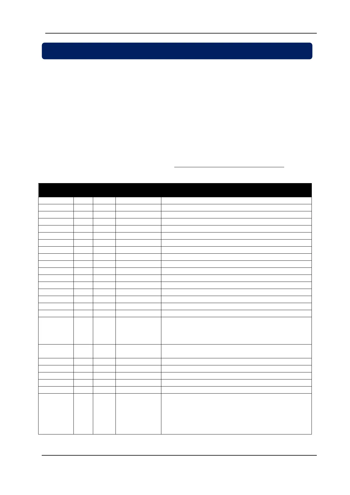
Below is a limited shortlist of readable registers. For the detailed Modbus Application
Manual and a complete list of registers please contact DATAKOM.
Genset active power: this 24 bit signed register holds
the genset active power multiplied by 256. Least
significant 16 bits are in the register 0016h. Most
significant 8 bits are in the LSB of the register 0017h.
Power factor multiplied by 100 (signed byte). Negative
values indicate a capacitive power factor.
Coolant temperature in degrees C.
bit_3: manual mode
bit_4: auto mode
bit_5: off mode
bit_6: test mode
bit_7: load test mode

 Loading...


