Do you have a question about the Datakom D Series and is the answer not in the manual?
Details the D-xxx series genset control units, highlighting multi-functionality and communication capabilities.
Lists the various operational modes and capabilities of the genset controller.
Outlines the available communication protocols and options for the unit.
Outlines essential safety precautions to prevent injury or damage during installation and operation.
Provides guidelines for proper installation, including pre-installation checks and potential damaging conditions.
Covers essential electrical installation practices, fuse ratings, cable selection, and grounding.
Details generator and mains phase inputs, neutral, contactors, and current transformer connections.
Provides comprehensive electrical, environmental, and physical specifications of the unit.
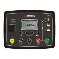
Identifies and explains the functions of the front panel elements like buttons, LEDs, and the display.
Details the specific actions performed by each button on the controller's front panel.
Lists all electrical and engine parameters that can be measured and displayed by the unit.
Explains the automatic transfer between genset and mains, including failure and restoration sequences.
Describes manual engine starting and load transfer control using front panel buttons.
Defines the three protection levels: Shutdown Alarms, Load Dumps, and Warnings.
Details critical fault conditions that cause immediate engine stop and alarm activation.
Describes fault conditions resulting in engine stop after cooldown or loaddump alarms.
Details how to disable protections for specific scenarios, with associated warnings.
Provides the procedure to restore the controller to its original factory settings.
Explains how to access the programming menu, including password entry.
Guides the user through the two-level menu system for accessing and modifying parameters.
Covers parameters for display settings, language, prompts, timers, and operational modes.
Includes settings for voltage, frequency, current limits, phase order, and topology.
Details parameters related to engine RPM, temperature, oil pressure, and starting sequences.
Covers APN settings, SIM card pin, SMS, and GPRS enabling for GSM modem.
Explains how the unit detects engine conditions to stop cranking reliably.
Details the Inverse Definite Minimum Time protection against excessive currents.
Explains the interface for communicating with electronic engines via J1939 protocol.
Explains the available SMS commands for remote control and information retrieval.
Allows scheduling of genset operation based on time of day and week.
Addresses issues like incorrect AC voltages, faulty KW/cosΦ readings, and engine start failures.
Covers problems such as delayed cranking, no start after AC mains failure, and genset not taking load.
| Category | Controller |
|---|---|
| Series | D Series |
| Digital Inputs | 6 |
| Humidity | 95% non-condensing |
| Weight | 0.3 kg |
| Communication Ports | RS-485 |