DS2400N QUICK GUIDE
3
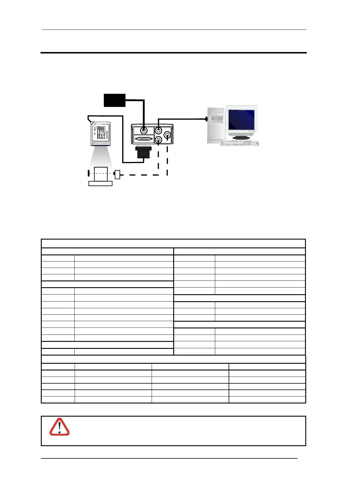
STEP 1 – CONNECT THE SYSTEM
To connect the system in a Stand Alone configuration, you need the hardware indicated in Figure 1. In this layout
the data is transmitted to the Host on the main serial interface. In Local Echo communication mode, the RS232
auxiliary interface can be used to transmit data independently from the main interface selection. When On-Line
Operating mode is used, the scanner is activated by an External Trigger (photoelectric sensor) when the object
enters its reading zone.
Figure 1 – DS2400N in Stand Alone Layout
CBX100/500 Pinout for DS2400N
The table below gives the pinout of the CBX100/500 terminal block connectors. Use this pinout when the
DS2400N reader is connected by means of the CBX100/500:
CBX100/500 Terminal Block Connectors
Power Outputs
Vdc Power Supply Input Voltage + +V Power Source - Outputs
GND Power Supply Input Voltage - -V Power Reference - Outputs
Earth Protection Earth Ground O1+ Output 1 +
O1- Output 1 -
Inputs
O2+ Output 2 +
+V Power Source – External Trigger O2- Output 2 -
I1A External Trigger A (polarity insensitive)
Auxiliary Interface
I1B External Trigger B (polarity insensitive) TX Auxiliary Interface TX
-V Power Reference – External Trigger RX Auxiliary Interface RX
+V Power Source – Inputs SGND Auxiliary Interface Reference
I2A Input 2 A (polarity insensitive)
ID-NET™
I2B Input 2 B (polarity insensitive) REF Network Reference
-V Power Reference – Inputs ID+ ID-NET™ network +
Shield
ID- ID-NET™ network -
Shield Network Cable Shield
Main Interface
RS232 RS485 Full-Duplex RS485 Half-Duplex
TX TX+ RTX+
RTS TX- RTX-
RX
*RX+
CTS
*RX-
SGND SGND SGND
* Do not leave floating, see Reference Manual for connection details.
CAUTION
Do not connect GND, SGND and REF to different (external) ground references. GND, SGND
and REF are internally connected through filtering circuitry which can be permanently
damaged if subjected to voltage drops over 0.8 Vdc.
DS2400N
Host
PG 6000
P.S.*
* Presence Sensor
(for On-Line mode)
MAIN
I/O, AUX
CBX100/500

 Loading...